Advertisement
Available languages
Available languages
Quick Links
TH1 ユーザーズマニュアル / TH1 User manual
概要
1
2
安全上のご注意
2.1
使用目的
2.2
インストールと起動
2.3
接続を確認する
2.4
システムの電源を入れる
2.5
測定値を確認する
2.6
機能を確認する
2.7
故障誤動作
3
電気的データ
3.1
機械のアースとケーブルのシールド
3.2
EMC
3.3
溶接
4
インストール手順
5
配線
6
取付とインストール
6.1
フランジネジ M18x1.5
6.1.2
設置例
6.2
ポジションマーカー
7
電気接続
7.1
コード 101/103/108
7.2
コード 102/107
7.3
コード 201/203/205
7.4
ピン配置
8
インターフェースと接続の割り当て
8.1
Start-Stop- インパルスインターフェース
8.2
SSI インターフェース
8.3
DyMoS インターフェース
8.4
アナログ出力
8.5
IO-Link インターフェース
9
ティーチイン機能
10
ポジションマーカーの変位
10.1
エラー状態ポジションマーカー
11
注文コード
12
製品の識別
Page 1
1
2
2
2
2
2.1
2
2.2
2
2.3
2
2.4
2
2.5
2
2.6
2
2.7
3
3
3
3.1
3
3.2
3
3.3
4
4
5
4
6
5
5
6.1
6
6.1.2
7
6.2
7
7
7
7.1
7
7.2
7
7.3
8
7.4
8
9
9
8.1
9
8.2
10
8.3
10
8.4
11
8.5
9
11
10
12
10.1
12
11
12
12
12
General description
Safety instructions
Intended conditions of use
Installation & startup
Check connections
Turning on the system
Check measured values
Check functionality
Failure malfunction
Electrical data
Machine ground and cable shielding
EMC
Welding
Instructions for installation
Wiring
Mounting and installation
Screw flange M18x1,5
Installation example
Position marker
Electrical connection
Code 101/103/108
Code 102/107
Code 201/203/205
Contact arrangement
Interfaces and Connection Assignment
Start-Stop-Impulse interface
SSI interface
DyMoS interface
Analog output
IO-Link interface
Teach-In function
Displacement of the position marker
Error conditions position marker
Ordering code
Product identification
2
2
2
2
2
2
2
2
2
3
3
3
3
4
4
5
5
6
7
7
7
7
7
8
9
9
9
10
10
11
11
12
12
12
12
Advertisement

Related Manuals for novotechnik TH1 Series


Summary of Contents for novotechnik TH1 Series
- Page 1 TH1 ユーザーズマニュアル / TH1 User manual 概要 General description 安全上のご注意 Safety instructions 使用目的 Intended conditions of use インストールと起動 Installation & startup 接続を確認する Check connections システムの電源を入れる Turning on the system 測定値を確認する Check measured values 機能を確認する Check functionality 故障誤動作 Failure malfunction 電気的データ Electrical data 機械のアースとケーブルのシールド...
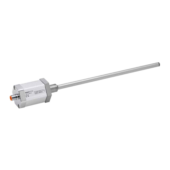
- Page 2 TH1 ユーザーズマニュアル / TH1 User manual 1 概要 1 General description TH1 シリーズは、制御、調整に用いられる高精度アブソリュートタイプの The TH1 series is a magnetostricitve transducer for direct, 磁歪変位トランスデューサです。 accurate measurement of travel in display- or feedback applications. 2 安全上のご注意 2 Safety instructions 当社の製品は、航空または航空宇宙用途では定期的に承認されておらず、 Our products are regularly not approved for aeronautic or aerospace applications and are not allowed to be used in 原子力または軍事、特に...
- Page 3 TH1 ユーザーズマニュアル / TH1 User manual 3 電気的データ 3 Electrical data 供給電圧 : 24 VDC ( データシートも参照 ) Supply voltage: 24 VDC ( see also data sheet) 消費電流 : < 100mA、 無負荷 Current consumption: < 100mA typical, without load 負荷 : 電圧出力≥ 5 ㏀ Load R : voltage output ≥ 5 ㏀ ...
- Page 4 TH1 ユーザーズマニュアル / TH1 User manual 4 インストール手順 4 Instruction for installation シリンダー内での直接ストローク測定の場合、ポジションマーカーはシリンダーのピス For direct stroke measuring in a cylinder the position marker has to be fixed with 2 screws M3 or M4 (depending on the トン底部に直接 2 本のネジ M3 または M4(ポジションマーカーに応じて)で固定する position marker) directly on the cylinder ‘s piston bottom, 必要があります。...
- Page 5 TH1 ユーザーズマニュアル / TH1 User manual 6 インストール / Installation 6.1 フランジネジ M18x1.5 / Screw flange M18x1,5 30mm にゼロ点がある機械的バージョン コード 102 または 106 コード コード アクセサリ ポジションマーカー Z-TH1-P18、Z-TH1-P19、Z-TIM-P20 ポジションマーカー Z-TH1-P25 のみ:電気的ゼロ点:29.25 mm 51mm にゼロ点がある機械的バージョン コード 104 または 108 コード コード アクセサリ ポジションマーカー Z-TH1-P18、Z-TH1-P19、Z-TIM-P20 オーリング 詳細 代替スレッド 3/4 "– 16UNF ポジションマーカー...
- Page 6 TH1 ユーザーズマニュアル / TH1 User manual 設置例 オーリング シリンダー ピストン付きピストンロッド 標準ケーブルの最小曲げ半径 50mm(φ 6 ± 0.2) アクセサリ 4 cap 参照 ポジションマーカー Z-TH1-P18、Z-TH1-P19、Z-TIM-P20 詳細 X, 磁化できない素材 詳細 X, 磁化可能な素材 ポジションマーカー 磁化できないスペーサ― ポジションマーカー オーリング オーリング 電気的ゼロ点 電気的ゼロ点 詳細 Y ISO 6149 に準拠したネジプラグ穴 (O リングシールなしで表示) Page 6...
- Page 7 TH1 ユーザーズマニュアル / TH1 User manual 6.2 ポジションマーカー / Position marker φ 11 22.5 スペーサ―付き TMI シリーズのポジションマーカー、Z-TMI-P02 および -P14 は、 TH1 シリーズのポジションマーカー(Z-TH1-P18 および -P19) と技術的に同一ではありません。 電気接続 /Electrical connention コネクタ コネクタ ケーブル 最少曲げ半径 50mm Page 7...
- Page 8 TH1 ユーザーズマニュアル / TH1 User manual 7.4 ピン配置 /Contact arrangement (フランジコネクタの正面図 /front view to the flange connector) 8 ピンフランジコネクタ 注文コード アクセサリ ストレートコネクタ アングルコネクタ 8 ピンフランジコネクタ 注文コード ストレートコネクタ アクセサリ アングルコネクタ 7 ピンフランジコネクタ 注文コード ストレートコネクタ ご要望により アクセサリ アングルコネクタ ご要望により 6 ピンフランジコネクタ 注文コード アクセサリ...
- Page 9 TH1 ユーザーズマニュアル / TH1 User manual 8 インターフェースと接続の割り当て / Interfaces and Connection Assignment 8.1 Start-Stop- インパルスインターフェース / Start-Stop- Impulse Interface 注文コードの例 /Example ordering code: TH1- _ _ _ _ - _ _ _ -11_ -_ _ _ 電気接続 /code electr. connection 8 ピンプラグ...
- Page 10 TH1 ユーザーズマニュアル / TH1 User manual 8.3 DyMoS インターフェース / DyMoS Interface 注文コードの例 /Example ordering code TH1- _ _ _ _ - _ _ _ -13 _ -_ _ _ 電気接続 /code electr. connection DyMoS 8 ピンプラグ 8 ピンプラグ w.cable ケーブル...
- Page 11 Example ordering code TH1- _ _ _ _ - _ _ _ -A_ _ -107 The description of IO-Link interface IO-Link インターフェースの説明 (…IO-Link_Detail)およびデバイス記述ファイル(IODD)は、 (…IO-Link_Detail) and the device description file (IODD) can be downloaded from Novotechnik website, NovotechnikWeb サイトからダウンロードできます。 see Downloads/Operating manuals ダウンロード / 操作マニュアルを参照してください。 => Click on TH1 =>...
- Page 12 ミリ単位 電気的インターフェース 機械的構成 コネクタ、8 ピン コネクタ、6 ピン フランジネジ コネクタ、5 ピン コネクタ、4 ピン コネクタ、7 ピン 電圧出力 ケーブル 電流出力 製品の識別 ネームプレート 注文コード バッチコード 製造元からなるシリアル番号 日付年週 YYWW / 連番 ■各種お問合せ ㈱ビー・アンド・プラス 〒 355-0311 埼玉県比企郡小川町高谷 2452-5 ㈱ビー・アンド・プラスは novotechnik 社の正規日本代理店です。 E-mail:NovotechnikJP@b-plus-kk.jp T621306Aj 2021.03.30 Page 12...
Need help?
Do you have a question about the TH1 Series and is the answer not in the manual?
Questions and answers