
Related Manuals for Massoth eMOTION LS


Summary of Contents for Massoth eMOTION LS
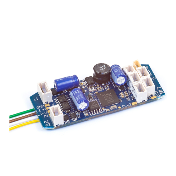
- Page 1 LS Bedienungsanleitung eMOTION LS User Manual Wichtige Information zur Inbetriebnahme Important setup information...
- Page 2 FREILANDTAUGLICHKEIT SUITABILITY FOR OUTDOOR USE Sehr geehrte Kunden, immer wieder errei- Dear customer, we have received a chen uns Anfragen bezüglich „rostender number of enquiries about rusty screws Schrauben“ bei Komponenten, die im in components that are used outside and Außenbereich der alljährlichen Witterung exposed to the elements.
-
Page 3: Table Of Contents
Sie sich VOR dem Anschluss der Lampen value before hooking up any lights or other und Funktionsausgänge das die Spannung accessories. Massoth cannot be responsible entsprechend der CV-Liste richtig eingestellt for any damage if this is disregarded. ist! Für Schäden durch Nichtbeachtung dieses Hinweises übernehmen wir keine... - Page 4 Wichtige Grundeinstellungen....Basic factory default settings....Programmierung........Programming........... Programmierspere CV 15/16....Programming Lock CV 15 / 16....Programmieradresse CV 107/108.... Programming Address CV 107 / 108..Lokadresse..........Locomotive address......... Anschluss und Funktion......Connections and functions....... Licht- und Funktionsausgänge....Light- and function outputs...... Automatic Uncoupler.......
-
Page 5: Summary Of Functions
Drehzahlregelung, Steuereingänge RPM control, control in- und Steuerausgang.......... and outputs..........Resetfunktion........... Reset functions......... Programmierung mittels PC und...... Programming via PC and Softwareupdate..........software update........CV Tabellen............CV Table............ Technische Daten..........Technical Data.......... Garantie, Reparatur, Kundendienst....Warranty, Service, Support....... Hotline.............. Hotline............1. - Page 6 600mA (A1-4), 2 mit je 10mA mAmps each (A1-4), 2 with 10mA (A7+8)) each (A7+8)) • Licht- und Funktionsausgänge • Light and function outputs may be dimmbar und analog aktivierbar dimmed + activated in analog mode • Programmierbare Blinklicht-, • Programmable blinking light, short- Impuls- und Taktgeberfunktion time function, and pulse generator •...
-
Page 7: Scope Of Supply
Funktionen kurzge- destroyed subsequently. schlossen, kann diese Sicherung To mount the eMOTION LS use our nicht wirken und der Decoder wird decoder bracket (# 8104010) zerstört. Zur Befestigung empfehlen Use a small soldering iron to prevent... -
Page 8: Motor And Track Connection
Fahrtrichtung links Gleis (+). left in direction of travel (LGB only)! Abbildung 1: Anschluss an Motor + Gleis Illustration 1: Installation of the eMOTION LS Sound Decoder Die angegeben Kabelfarben können The stated wire colores may differ vom Aufdruck am Getriebe abwei-... -
Page 9: Connection Of Speaker
Gleis + ge = Motor + Fahrtrichtung ws = Gleis + br = Gleis - gn = Motor - Gleis - Abbildung 2: Anschluss an ein LGB Getriebe Illustration 2: Installation on a LGB gear box 2.3 Lautsprecheranschluss 2.3 Connection of speaker An die Lautsprecher-Buchse wird The 8 Ohm loudspeaker is con- der 8 Ohm Lautsprecher ange-... -
Page 10: Advanced Settings
3. Erweiterte Einstellungen 3. Advanced settings 3.1 Anschlüsse auf der Oberseite 3.1 Terminals on the upper side Lautsprecher Speaker LI-V/LI-F Dec- Dec+ LI-I LI-H/LI-R Dec+ Dec- Dec- LI-H/LI-R Poti LI-V/LI-F Dec+ Dec+ Dec- Taktgeber Takt/Clock Clock +6,5V Abbildung 4: eMOTION Decoder Anschlüsse Illustration #4: eMOTION contact assignment Dec- Masse (-) - Page 11 Auf der Oberseite des eMOTION LS The eMOTION LS Sound Decoder Sounddecoders (Abb. 4) sind sieben features seven additional connectors zusätzliche Anschlussbuchsen on the upper side (illustration #4). vorhanden. • Taktgeber: Anschluss für einen • Clock: connector for an external externen Taktgeber. Benutzen Sie pulse generator.
-
Page 12: Connectors On The Lower Surface
3.2 Anschlussflächen a.d. Unterseite 3.2 Connectors on the lower surface Dec- Motor- Gleis- Gleis+ Dec- Motor+ Reed 1 Dec+ Reed 2 CLK2 Abbildung 5: eMOTION Dekoder Anschlüsse unten Illustration #5: eMOTION contact assignment lower surface track (-) brown wire to the motor Gleis (-) Braunes Kabel zum block Getriebeanschluss... - Page 13 Connector for second pulse gen. Auf der Unterseite des eMOTION Some more contacts are located on LS Sounddecoders sind mehrere the lower side of the eMOTION LS Anschlüsse angebracht. Sound Decoder. • Getriebeanschlusskabel: Mit den 4 • Motor Cables: The LS Sound...
-
Page 14: Installation
4.2 Einbau mit LGB DCC Schnittstelle 4.2 Installation with LGB DCC Interface Unter Artikelnummer 8211098 ist The eMOTION LS Decoder is available der eMOTION LS Sounddecoder with the 10-pin DCC plug for the LGB mit 10-poligem Schnittstellenkabel, DCC interface under #8211098. -
Page 15: Installation With Lgb Decoder Interface
Mit dem LGB Schnittstellenkabel Using the LGB decoder interface ® ® kann der Decoder zusätzlich an cable the eMOTION LS can be easily Loks mit der Decoderschnitt- installed in LGB locomotives with ® ® stelle eingebaut werden (Abb. a decoder interface (Illustr. #7). The 7). -
Page 16: Light And Function Outputs
4.4 Licht und Funktionsausgänge 4.4 Light and function outputs Der eMOTION LS verfügt über The eMOTION LS Sound Decoder verschiedene Licht- und Funkti- features 3 light outputs, front light, onsausgänge. Es befinden sich 3 rear light, and interior light. The Lichtanschlüsse auf dem Decoder. - Page 17 spannung eingestellt (einstellbar in well as the voltage of output A1-A4 CV 50, 53, 112). Die Ausgänge 7+8 may be programmed by setting the haben nur eine Spannung von 5 Volt respective CV’s. For details please und dürfen mit max. 10 mA belastet review the CV-table.
-
Page 18: Power Buffer (Bc)
4.5 Spannungspuffer (BC) 4.5 Power buffer (BC) Der eMOTION LS besitzt einen The eMOTION LS features a separate 3-poligen Lötanschluss für Span- connector for power buffers nungspuffer (8151601 + 8151701). (Massoth 8151601 + 8151701). Massoth Powercaps besitzen The power buffer bridges brief power eine zusätzliche Steuerleitung, die... -
Page 19: Reed Contacts To Trigger Bell And Whistle By Track Magnets
SUSI norm. 5. Inbetriebnahme 5. Getting started Das Konzept des eMOTION LS legt eMOTION LS Decoders are designed großen Wert auf einfache Ein- for easy handling and installation. To bau- und Anschlussmöglichkeiten,... -
Page 20: Basic Factory Default Settings
Soldering is not required. 5.1 Wichtige Grundeinstellungen 5.1 Basic factory default settings Die Grundeinstellungen des This table shows the basic factory eMOTION LS Decoders sind wie default settings of the eMOTION S: folgt: Basic settings sound decoder (S) Grundeinstellung der SoundDecoder (LS) -
Page 21: Programming
Für die Programmierung muss der All CVs may be programmed if the Decoder an einen Motor angeschlos- eMOTION LS decoder is connected to sen sein. Ein kurzes Zucken am Motor a motor. A brief twitch of the motor quittiert dabei den Programmierpro- acknowledges the programming zess. -
Page 22: Programming Address Cv 107 / 108
Adresse 10239. 5.5 Lokadresse 5.5 Locomotive address Wird der eMOTION LS Decoder in In case the eMOTION LS Decoder is Verbindung mit anderen Decodern used in connection with third party verwendet, muss die Programmie- decoders, the address must be pro- rung der Adresse vorab erfolgen. -
Page 23: Connections And Functions
• A4: CV 115 auf Wert 31 (immer an) • A4: CV 115 with value 31 (always on) Entkuppler Uncoupler Entkuppler Uncoupler Abbildung 10: Anschlüsse für Automatische Entkuppler am eMOTION LS Illustration #10: Connections for Automatic Uncoupler on the eMOTION LS... -
Page 24: Rc Servo Function
6.3 Servofunktion 6.3 RC Servo function Ausgang 7 kann zur Steuerung eines Output 7 may be utilized to control an Servos genutzt werden. In CV 124 RC servo. This function is activated wird die Sondernutzung aktiviert. Mit with CV 124. CV 125 and CV 126 de- CV 125 + 126 wird der Drehbereich fine the turning range. -
Page 25: Bus Connection
6.6 Busanschluss (CV 49) 6.6 Bus Connection • Massoth/LGB-Bus • Massoth/LGB bus Über den Massoth Bus bekommt der The Massoth bus provides the LS Decoder folgende Informationen: following information: Acceleration, Anfahren, Anhalten und Lastzustand. stopping, load condition. • SUSI-Bus • SUSI bus Über den SUSI-Bus bekommt der... -
Page 26: The Sound On The Decoder
8. Soundfunktionen 8. The Sound in the decoder Der eMOTION LS Sounddecoder gibt The eMOTION Sound Decoder den Funktionsumfang einer Lokomo- contains a full fledged digital tive in hoher Qualität realistisch wie- power amplifier which reproduces der. Dabei beschränkt sich der eMO-... -
Page 27: Driving Sounds
LS Soundecoder verfügt über bis which are assigned to the F-keys. Be- zu 12 Geräusche, die einzelnen sides the sounds other functions are Funktionstasten zugeordnet sind. assigned, e.g. sound on/off, accel./ Neben diesen Geräuschen sind auch deceleration on/off, switching speed Funktionen, wie z.B. -
Page 28: Additional Sounds
Da es viele Unterschiede bei den totype. The functionality of the sound Vorbilder gibt, variiert der Funktions- decoder may vary significantly due to umfang des Sounddecoders teilweise the wide range of original prototype deutlich. Details entnehmen Sie bitte features. For details please see the dem Soundprojekt zugeordneten sound project associated sound data Sounddatenblatt. -
Page 29: Automatic Sounds
Funktionstaste wird der Sound is switched off again. The volume eingeschaltet. Dieser wird so lange of each sound may be programmed wiederholt bis die Funktionstaste separately in steps of four: erneut geschaltet wird. Jeder Sound 3 = max. volume kann in der Lautstärke in 4 Stufen 2 = ¾... -
Page 30: Operation Noises
8.4.2. Schaltgeräusche (ab V2.2) 8.4.2. Operational noises (since V2.2) Bei z.B. einer E-Lok ist beim Be- During acceleration a multiple contact schleunigen der Stufenschalter zu hö- switch is operated in an electric lo- ren. Das verwendete Schaltgeräusch comotive. The sound used is defined wird in CV 234 eingetragen. -
Page 31: Random Generator
8.5 Function key assignment 8.5 Funktionstastenzuordnung The settings for the sound in the Ab CV 131 werden die Soundeinstel- eMOTION LS Decoder start at CV lungen des eMOTION LS Decoder 131. In this section specific sounds vorgenommen. Hier werden unter... -
Page 32: Function Key For Steam Rack Rail Loco
Der Sounddecoder bietet die (CV 201 - CV 212) Möglichkeit die Lautstärke per CV- The eMOTION LS Decoder features Programmierung einzustellen. So volume control by CV-programming. kann direkt während des Betriebs die The volume of the sound may Lautstärke per POM geändert wer-... -
Page 33: Volume Control Driving Sounds
8.8 Lautstärkeeinstellung Fahrge- 8.8 Volume Control Driving Sound (CV räusche (CV 217 – CV 220) (V 1.3) 217 – CV 220) (since V1.3) • Bei einer Dampflok • Steam Locomotive - CV 217 --- - CV 217 --- - CV 218 Standrauschen - CV 218 Standing noise - CV 219 Zylindernebengeräusche - CV 219 Cylinder side noises... -
Page 34: Loudspeaker + External Volume Control
If you incre- größer als den Mittelwert ein. Wenn ase the track voltage until the sound Sie die Spannung hochregeln, bis starts, the eMOTION LS Decoder will das Geräusch ertönt, erkennt die recognize the external volume control Elektronik das Poti und programmiert and subsequently will program CV die CV 200 um auf 255. -
Page 35: Loudspeaker Specs
9.4 Lautsprecherkenndaten 9.4 Loudspeaker specifications Die Verstärkerendstufe des eMOTION The output stages of the eMOTION LS Decoder leistet 1 - 3 Watt bei 8 LS Decoders are rated between 1 and Ohm Impedanz. Betreiben Sie nur 3 Watts at an impedance of 8 Ohms Lautsprecher mit dieser Spezifikation! (depending on the decoder type). -
Page 36: Rpm Control, Control In- And Outputs
10. Drehzahlregelung, Steuereingänge 10. RPM control, control in- and outputs und Steuerausgänge The synchronization of the sound Die Synchronisation des Sounds with the rotation of the wheels can mit der Radumdrehung kann einmal be achieved with a pulse generator mittels Fahrstufe oder mit einem or by speed steps. -
Page 37: Reset Functions
12. Programming via PC und Softwareupdate and software update Die eMOTION Sounddecoder und The eMOTION LS Decoders (with Soundmodule können ab Version 2.0 version 2.0 and higher) may be über das DiMAX PC Programmiermo- updated with the DiMAX PC module. -
Page 38: Cv Table
CV - Tabelle (Fahreinstellungen) Diese Tabelle zeigt die Standardeinstellungen. (S = Standard, A = Analogbetrieb) Konfigurationsvariablen (CV-Tabelle) CV Beschreibung A Bereich Bemerkung Lokadresse (standard kurz) 1... 127 wenn CV 29, Bit 5 = 0 Anfahrspannung (in Fahrstufe 1) 1... 255 CV 2 x (1/255 Gleisspannung) Anfahrverzögerung √... - Page 39 CV - Table (drive settings) This table shows the standard settings of the S-decoder. (D = Default, A = analog operation) Table of configuration variables CV Description Range Note: Loco address (Standard short) 1... 127 If CV 29 bit 5 = 0 Starting voltage 1...
- Page 40 CV Beschreibung A Bereich Bemerkung 19 Mehrfachtraktionsadresse 1... 99 29 NMRA Konfiguration √ siehe Anhang 1 49 MASSOTH Konfiguration √ siehe Anhang 2 50 Licht: Dimmwert (PWM) √ 1... 32 32 = volle Gleisspannung 51 Licht vorne Schaltbefehl siehe Anhang 3...
- Page 41 Range Note: 19 Multiple Unit Address 1... 99 29 Configuration Table NMRA √ see attachment 1 49 Configuration Table MASSOTH √ see attachment 2 50 Light: Dimming Value (PWM) √ 1... 32 32 = full track voltage 51 Front Light: Command Allocation...
- Page 42 Konfigurationsvariablen (CV-Tabelle) CV Beschreibung A Bereich Bemerkung 114 A3 Sonderfunktion √ siehe Anhang 4 + 5 115 A4 Schaltbefehl siehe Anhang 3 116 A4 Sonderfunktion √ siehe Anhang 5 + 5a 121 A7: Schaltbefehl 0 ... 16 0 = Licht 1 ... 16 = Funktionstaste 123 A8: Schaltbefehl 0 ...
- Page 43 Table of configuration variables CV Description Range Note: 114 A3 Special function √ see attachment 4 + 5 115 A4 Command allocation 116 A4 Special function 121 A7 Switching function 0 ... 16 0 = Light 1 ... 16 = Function key 123 A8 Switching function 0 ...
- Page 44 S Bereich Bemerkung 147 Sound An/Aus: Schaltbefehl 0...16 Ab-/Aufrüsten 0...16 Zylindernebengeräusch bei Dampfloks 149 Massoth Soundkonfiguration 0...255 siehe Anhang 7 150 Anfahrsperre während des Aufrüstens 0... 3 0=Aus, 1=Dig., 2=An., 3=Dig.+An. 151 Zusatzsound 1: Loopanzahl 0...16 0 = keine Soundwiederholung 152 Zusatzsound 2: Loopanzahl 0...16...
- Page 45 147 Amplifier (Sound) Off/On : Switch. com. 0...16 Loco start up/shut down, resp. cylinder 0...16 sound (Steam engine) 149 Configuration register Massoth-sound 0...255 see attachment 7 150 Starting Inhibit between startingphase 0... 3 0=off, 1=dig., 2=an., 3=dig.+an. 151 Add. sound 1 : Number of loops 0...16...
- Page 46 Konfigurationsvariablen (CV-Tabelle) CV Beschreibung S Bereich Bemerkung 175 1. Standgeräusch: Loopanzahl 0...15 0 = keine Soundwiederholung Der Sound wird 1x abgespielt. 176 2. Standgeräusch: Loopanzahl 0...15 1 ... 15 = Anzahl der Wiederho- 177 3. Standgeräusch: Loopanzahl 0...15 lungen z.B. Anzahl Luftpumpen- 178 4.
- Page 47 Table of configuration variables CV Description A Range Note 0...15 0= no sound repetition: 175 1. Standing noise : Number of loops the sound will be triggered only 176 2. Standing noise : Number of loops 0...15 once / 1…15: number of repeti- 177 3.
- Page 48 Konfigurationsvariablen (CV-Tabelle) CV Beschreibung S Bereich Bemerkung 201 Individuelle Lautstärke: Zusatzsound 1 0...3 0 = Reduzierung auf 25% 1 = Reduzierung auf 50% 202 Individuelle Lautstärke: Zusatzsound 2 0...3 2 = Reduzierung auf 75% 203 Individuelle Lautstärke: Zusatzsound 3 0...3 3 = Volle Lautstärke 100% 204 Individuelle Lautstärke: Zusatzsound 4 0...3 205 Individuelle Lautstärke: Zusatzsound 5...
- Page 49 Table of configuration variables CV Description A Range Note 201 Add. sound 1: Individual volume level 0...3 0= 25% volume level 1= 50% volume level 202 Add. sound 2: Individual volume level 0...3 2= 75% volume level 203 Add. sound 3: Individual volume level 0...3 3= 100% maximum volume 204 Add.
- Page 50 Anhang 2: CV 49 - MASSOTH Konfigurationsregister Bit Wert AUS (Wert 0) Bemerkung nur parallele parallele + serielle Seriell/Parallel wird bei Funktionsdatenverarbeitung Funktionsdatenverarbeitung „An“ automatisch erkannt digitale Lastregelung AUS digitale Lastregelung AN analoge Lastregelung AUS analoge Lastregelung AN Massoth Bus SUSI Bus Feststellbremse AUS Feststellbremse AN...
- Page 51 Parallel data transfer only Serial + parallel data transfer of serial/parallel Digital load control = OFF Digital load control = ON Analog load control = OFF Analog load control = ON Massoth bus SUSI bus electronic parking brake OFF electronic parking brake ON...
- Page 52 Anhang 3: CV 51, 52, 54, 56, 113, 115 Schaltbefehlszuordung Licht vorn / hinten, A1, A2, A3, A4 Wert Verwendung Bemerkung 0 = Schalten mit der Lichttaste 0... 16 1 ... 16 = Schalten mit der Funktionstaste Schaltausgang immer an nur A2, A4 (0...
- Page 53 Attachment 3: CV 51, 52, 54, 56, 113, 115 Switch output commands Light front / rear, A1, A2, A3, A4 Value Application Note 0 = Switch function with light key, 0... 16 1 ... 16 = Switch function with F-key No. 1-16 Switching output always on only A2, A4 (0...
- Page 54 Anhang 6: CV 124 - Servofunktion A7 Wert Verwendung Bemerkung 0 = Servo deaktiviert Normaler Schaltausgang 1 = Servo aktiv Pegel invertiert Abschaltung nach Bewegung Anhang 7: CV 149 - MASSOTH Soundkonfiguration Bit Wert AUS (Wert 0) Bemerkung Zufallsgenerator AUS Zufallsgenerator AN Standgeräusch AUS Standgeräusch AN Normales Fahrgeräusch Lastabhäng.
- Page 55 Application Note 0 = Servo deactivated regular switching output 1 = Servo activated Control level inverted Switch-off after movement Attachment 7: CV 149 - MASSOTH Sound Configuration Bit Value OFF (Value 0) Note Random generator OFF Random generator ACTIVE Standing phase noise OFF Standing phase noise ACTIVE...
- Page 56 Anhang 8: CV-Werte bei Decoder-Resetfunktion Resetwert 13 112 113 114 121 123 124 125 126 127 129 130 CV 131 – CV 167 Reset Soundfunktionen CV 171 – CV 199 Reset Standphase CV 200 – CV 220 Reset Lautstärkeeinstellungen (+ CV221 - CV 224 bei Zweikraftlok) Anhang 9: Grundwerte der frei programmierbaren Fahrkurve (CV 67 - 94) Wert Wert 76...
- Page 57 Attachment 8: Default settings at resets Reset value 13 112 113 114 121 123 124 125 126 127 129 130 CV 131 - CV 167 Reset soundfunctions (Values depends on type of sound) CV 171 - CV 199 Reset standing phase (Values depends on type of sound) CV 200 - CV 220 Reset sound volume settings (+ CV 221 - CV 224 two force locomotives) Attachment 9: Basic values of freely programmable driving curve (CV 67 - 94)
-
Page 58: Technical Data
14. Garantie, Reparatur, Kundendienst 14. Warranty, Service, Support MASSOTH gewährt die Fehlerfreiheit MASSOTH warrants this product dieses Produkts für ein Jahr. Die against defects in materials and gesetzlichen Regelungen können workmanship for one year from in einzelnen Ländern abweichen. -
Page 59: Hotline
Behandlung oder Fremdeingriff nufacturer. Return shipping charges oder Veränderung des Produkts are not covered by MASSOTH. Please besteht kein Garantieanspruch. Der include your proof of purchase with Anspruch auf Serviceleistungen the returned goods. - Page 60 Massoth Elektronik GmbH QUALITY Frankensteiner Str. 28 · D-64342 Seeheim · Germany MADE IN FON: +49 (0)6151-35077-0 · FAX: +49 (0)6151-35077-44 GERMANY eMail: info@massoth.de · www.massoth.de...
Need help?
Do you have a question about the eMOTION LS and is the answer not in the manual?
Questions and answers