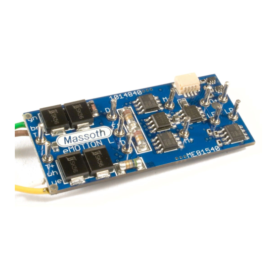
Massoth eMOTION M Connection Manual
Hide thumbs
Also See for eMOTION M:
- Configuration manual (40 pages) ,
- Manual (16 pages) ,
- Manual (16 pages)
Summary of Contents for Massoth eMOTION M
- Page 1 M Anschlussanleitung eMOTION M Connection Manual Art.-Nr. / Item No.: 8154501 Version 2.3...
- Page 2 This manual describes Beachten. In diesem Handbuch soll der the installation of the eMOTION M Anschluss des eMOTION M Lokdeko- decoder. ders erläutert werden. HINWEIS: Funktionsausgänge...
-
Page 3: Table Of Contents
Anschlüsse auf der Unterseite..Terminals on the lower side..... Licht- und Funktionsausgänge..Light- and function outputs..... Einbau in Loks ohne Schnittstelle..Installation without interface.... Anschluss SUSI/Massoth Bus..Using the SUSI/Massoth bus... Technische Daten......Technical Data......... Garantie, Reparatur, Kundendienst.. Warranty, Service, Support....Hotline..........Hotline.......... -
Page 4: Grundlegende Information
1. Grundlegende Informationen 1. General Information Wir empfehlen beide Anleitungen We recommend to read this manual gründlich zu lesen, bevor Sie den neuen carefully before the decoder is installed Dekoder in Betrieb nehmen. and operated. Einige Funktionen sind nur mit der Some functions require the latest firm- aktuellsten Firmware nutzbar, führen Sie ware for availability. -
Page 5: Lieferumfang
• Resetfunktion für alle CV-Werte • Firmware easy to be updated • Firmware updatefähig 1.2 Lieferumfang 1.2 Scope of Supply • eMOTION M Dekoder mit Getriebean- • eMOTION M Decoder with motorblock schlusskabel connecting cable • Klebepad • Double-sided tape •... -
Page 6: Inbetriebnahme
2. Inbetriebnahme 2. Hook-Up Bauen Sie den Dekoder sorgfältig Install your decoder in compliance with nach den Anschlussplänen in dieser the connecting diagram in this manual. Bedienungsanleitung in die Lok ein. Der The decoder is protected against shorts Dekoder ist generell gegen Kurzschlüsse and excessive loads. -
Page 7: Einbau
2.2 Einbau 2.2 Installation Sie können den Dekoder mit dem beilie- You may mount the decoder with either genden Klebepad befestigen. the supplied double-sided tape or with Alternativ können Sie den Dekoder über two screws using the mounting holes. die beiden Löcher festschrauben. Caution: Make sure that there is no Achten Sie beim Befestigen darauf, das short circuit caused by the mounting... -
Page 8: Anschlüsse Auf Der Unterseite
Licht vorne (-) front light (-) Licht hinten (-) rear light (-) Gemeinsamer Anschluss (+) Common terminal (+) for Dek+ Dek+ für Lampen- und light and function Funktionsausgänge outputs Funktionsausgang 1 (-), div. function output 1 (-), some Blinkfunktionen, Impuls flashing functions, pulse Funktionsausgang 2 (-), div. -
Page 9: Licht Und Funktionsausgänge
Funktionsausgang 6 (-), function output 6 (-), Ausgang Taktgeberfunktion output for pulse simulation [Takt] [chuff] Busanschluss DataOut (Für bus terminal Data-Out Massoth-Bus) oder [SuSi- (for Massoth-bus) or Clock] [SuSi-clock] Busanschluss DataIn (Für bus terminal Data-In Massoth-Bus) oder [SuSi- (for Massoth-bus) or... -
Page 10: Einbau In Loks Ohne Schnittstelle
Abbildung 3: Verschaltung der Licht- und Funktionsausgänge (Glühbirnensymbol steht für allgemeinen Verbraucher) Illustration 3: Connection of the light- and function outputs (the bulb symbol stands for all regular loads) 3.4 Einbau in Loks ohne Schnitt- 3.4 Installation without interface stelle Generell lässt sich der Dekoder in Loks Installation in a locomotive without ohne Schnittstelle besonders einfach... -
Page 11: Anschluss Susi/Massoth Bus
Abbildung 5: Anschluss am Feldbahn Getriebe Illustration 5 : Hook-up at small diesel loco motor block 3.5 Anschluss SUSI/Massoth-Bus 3.5 Using the SUSI/Massoth bus Für den Anschluss eines SuSi-Bausteins The hook-up of SuSi-bus components müssen die 4 Kabel an den Dekoder requires soldering four wires to the angelötet werden. -
Page 12: Technische Daten
4. Technische Daten 4. Technical Data Spannungsversorgung: 0-24 V DC/DCC Power supply: 0-24 V DC/DCC (kurzzeitig max. 27V) (momentary max. 27V) Gesamtbelastbarkeit: Max. 2A Total load: Max. 2A Motorausgang: Max. 1,2A, 70Hz-16KHz, Motor output: Max. 1,2A, 70Hz-16KHz, lastgeregelt, Digital und Analog load controlled, digital and analog Lichtausgänge: Max. -
Page 13: Warranty, Service, Support
Eine Kopie Return shipping charges are not covered des Kaufbelegs wird vorausgesetzt. Für by MASSOTH. Please include your proof Schäden durch unsachgemäße of purchase with the returned goods. Behandlung oder Fremdeingriff oder Errors and changes excepted. -
Page 14: Hotline
4.2 Hotline 4.2 Hotline Serviceanfragen richten Sie bitte an: For technical support contact: Massoth Elektronik GmbH Massoth Elektronik GmbH, Germany Mo 14:00-17:30 sowie Do 8:00-12:00 Mo 2:00-5:30 p.m. Thu 8:00-12:00 a.m. FON +49 (0)6151-35077-38 FON +49 (0)6151-35077-38 FAX +49 (0)6151-35077-44 FAX +49 (0)6151-35077-44 hotline@massoth.de... - Page 15 Dieses Produkt entspricht den CE Konformitätsrichtlinien für elek- trische Kleingeräte in der aktuellen Fassung. This unit conforms to the CE Standards Dieses Produkt ist nach den aktuellen EG Richtlinien umgangssprach- lich „bleifrei“ hergestellt und damit RoHS-konform. RoHS This unit is manufactured according to the latest EG Standards for lead free manufacturing conforming to RoHS Standard.
- Page 16 Massoth Elektronik GmbH MADE Frankensteiner Str. 28 · D-64342 Seeheim · Germany FON: +49 (0)6151-35077-0 · FAX: +49 (0)6151-35077-44 GERMANY eMail: info@massoth.de · www.massoth.de...


Need help?
Do you have a question about the eMOTION M and is the answer not in the manual?
Questions and answers