Massoth eMOTION XLS Manual
Sound decoder
Hide thumbs
Also See for eMOTION XLS:
- Installation manual (24 pages) ,
- Parameter-setting manual (2 pages)
Table of Contents
Advertisement
Available languages
Available languages
Quick Links
Advertisement
Chapters
Table of Contents

Related Manuals for Massoth eMOTION XLS


Summary of Contents for Massoth eMOTION XLS
- Page 1 XLS Sounddekoder Version2.0 - 08/08 eMOTION XLS Sounddekoder...
- Page 2 Auslieferungszustand auf volle Gleisspannung eingestellt! Vergewissern Sie sich VOR dem Anschluss der Lampen und Funktionsausgänge das die Spannung entsprechend der CV-Liste (ab Seite 32) richtig eingestellt ist! Für Schäden durch Nichtbeachtung dieses Hinweises übernehmen wir keine Haftung. eMOTION XLS Sounddekoder...
-
Page 3: Table Of Contents
Inhaltsübersicht Seite 1.Sicherheitsrelevante Informationen zur Inbetriebnahme 1.1.Lieferumfang 2.Wichtige Informationen zur Inbetriebnahme 2.1.Anschluss 2.1.1.Anschlussbuchsen auf der Oberseite 2.1.2.Anschluss des eMOTION XLS an ein LGB ® Getriebe 2.2.Grundeinstellung des eMOTION XLS bei Auslieferung 2.3.Befestigung 3.Erweiterte Einstellungen 3.1.Anschlussbuchsen auf der Unterseite 3.2.Anschluss des eMOTION XLS an eine LGB ®... -
Page 4: Sicherheitsrelevante Informationen Zur Inbetriebnahme
11.1.Hersteller 1.Sicherheitsrelevante Informationen zur Inbetriebnahme Sehr geehrter Kunde, mit dem Kauf des eMOTION XLS Lokdekoders haben Sie sich für einen besonders leistungsfähigen Sounddekoder der Massoth Elektronik GmbH entschieden. Wir empfehlen, diese Produkt- dokumentation gründlich zu lesen, bevor Sie den neuen Sounddekoder in Betrieb nehmen. Die neuesten Entwicklungs- und Fertigungsstandards wurden bei der Entwicklung des eMOTION XLS Lokdekoders eingesetzt. -
Page 5: Lieferumfang
1.1.Lieferumfang Im Lieferumfang des eMOTION XLS Dekoders sind die folgend aufgelisteten Komponenten enthalten: eMOTION XLS Dekoder Handbuch Lautsprecher Schnittstellenkabel für LGB© Schnittstellenkabel für ARISTOCRAFT DCC 2 Befestigungsschrauben Sollte eine dieser Positionen im Lieferumfang nicht enthalten oder beschädigt sein, so informieren Sie bitte Ihren Fachhändler oder wenden Sie sich direkt an den Hersteller. -
Page 6: Anschluss
Einstellbare Nachlaufzeit bei Pufferbetrieb über CV-Wert • 2.1.Anschluss Der Einbau des eMOTION XLS Sounddekoders ist einfach. Im Lieferumfang des Sounddekoders befinden sich bereits die benötigten Anschlusskabel und Befestigungsmaterial. Die Belegung der Sounddekoderanschlüsse entnehmen Sie bitte der folgenden Abbildung. Beachten Sie die Auslieferungseinstellung der Funktionsanschlüsse F1 bis F6. -
Page 7: Anschluss Des Emotion Xls An Ein Lgb ® Getriebe
Getriebe (mit Ausnahme sehr alter Getriebe) verfügen über 4 Kontaktstifte auf der Oberseite des Getriebeblocks, an denen der eMOTION XLS Sounddekoder angeschlossen wird. Damit ist das Getriebe generell für den Digitalbetrieb geeignet. Ältere Getriebe sind eventuell nur mit 3 Kontaktstiften versehen. -
Page 8: Grundeinstellung Des Emotion Xls Bei Auslieferung
Hier finden Sie alle weiteren Funktionen, die der Dekoder neben den in 2.2 erwähnten Grundfunktionen bietet. 3.1.Anschlussbuchsen auf der Unterseite Auf der Unterseite des eMOTION XLS Sounddekoders sind zwei zusätzliche Anschlüsse angebracht. Es handelt sich dabei um Lötkontakte, an denen ein Anschluss für eine Infrarot-LED zur Datenübertragung und ein weiterer Funktionsausgang (F6) vorgesehen sind. -
Page 9: Anschluss Des Emotion Xls An Eine Lgb ® Schnittstelle
Hersteller genormte Digitalschnittstelle und sind für den Einbau von Digitalkomponenten vorbereitet. Wird der Sounddekoder in eine dieser Loks eingebaut, kann ein DCC Schnittstellenkabel zum Anschluss des eMOTION XLS Sounddekoders verwendet werden. Ziehen Sie dazu den Blindstecker von der Lokelektronik ab. -
Page 10: Massoth Busanschluss
Hier kann z.B. der Massoth-Verdampfer angeschlossen werden. 3.5.Licht- und Funktionsausgänge Der eMOTION XLS Sounddekoder verfügt über entsprechende Licht- und Funktionsausgänge. Wie bereits bewährt, befinden sich 3 Lichtanschlüsse auf dem Dekoder. Es handelt sich dabei um Frontlicht, Rücklicht und zusätzlich die Innenbeleuchtung. Die Front- und Rückbeleuchtung werden fahrtrichtungsabhängig geschaltet. -
Page 11: Anschluss Für Spannungspuffer
Der eMOTION XLS Sounddekoder verfügt zu den 3 Lichtanschlüssen zudem über 8 separate Funktionsausgänge, die unterschiedlich genutzt werden können. Auf der Oberseite befinden sich 5 Funktionsausgänge an den Klemmen, 2 weitere auf einer Buchse (F7/F8), ein weiterer befindet sich als Lötkontakt auf der Unterseite des Dekoders (F6). - Page 12 Abbildung 12: Interne Fahrkurve des eMOTION XLS Sounddekoders, einstellbar über CV2 (Anfahrspannung), CV5 (Maximalgeschwindigkeit), CV6 (Mittengeschwindigkeit) Neueste Dekoder wie dieser eMOTION XLS Sounddekoder verfügen über drei CV's, in denen die Geschwindigkeitsparameter definiert werden können. Im Auslieferungszustand ist der eMOTION XLS Sounddekoder auf die in der Zeichnung dargestellten Werte eingestellt.
- Page 13 Lastregelung funktioniert nur bei 24kHz. Der Dekoder ist auch für Glockenankermotoren geeignet. Lastregelung Die Lastregelung des eMOTION XLS Sounddekoders überwacht das Fahrverhalten der Lok und regelt die Motorspannung. Die Lastregelung hat die Aufgabe, die Geschwindigkeit der Lokomotive unabhängig von Steigung, Gefälle der Strecke oder Zuglänge konstant zu halten. Das bedeutet, dass der Dekoder bei einer Steigung den Motor selbsttätig mit einer höheren Motorspannung versorgt, damit die Lok ihre...
- Page 14 Die Nachregelverzögerung definiert, wie oft der Dekoder je Sekunde nachregeln darf. Dabei gilt, je kleiner dieser Wert, desto mehr Regelungen pro Sekunde finden statt. Der eMOTION XLS Sounddekoder kann bis zu 4000 Regelungen je Sekunde durchführen. Im Auslieferungszustand ist der Wert 60 eingestellt. Dies führt zu einem gemächlichen, und realistischen Regelverhalten.
-
Page 15: Spezielle Fahrfunktionen
Pausenzeit inaktiv. 3.9.Analogbetrieb Der eMOTION XLS Sounddekoder kann bereits ab wenigen Volt im vollen Umfang analog betrieben werden. Der Betrieb im Analogmodus kann mit CV29 - Bit2 gesperrt werden. Der Dekoder besitzt eine interne Motor-kennlinie, welche mittels Gleisspannungsmessung ein weiches Anfahren im Analogbetrieb ermöglicht. -
Page 16: Fahrgeräusche
Abhängig von der entsprechenden Vorbildlokomotive und den auf dem Sounddekoder abgelegten Sounds unterscheiden sich die CV-Einstellungen der Sounddekoder voneinander. Sound- und Funktionszuordnung Die Sounddekoder der eMOTION XLS Reihe sind in der Regel nach einem gleichmäßigen Muster eingerichtet. Das heißt, unabhängig vom Sound sind die Funktionen grundlegend gleich zugeordnet. Siehe hierzu Dekoderdatenblatt. -
Page 17: E-Lok
Bei z.B. einer E-Lok ist beim Beschleunigen der Stufenschalter zu hören. Welches Schaltgeräusch verwendet wird, wird in CV234 eingetragen. Bei welcher Geschwindigkeit die Ausgabe erfolgt, wird in den CV's 230, 231 für Digitalbetrieb und CV232 und CV233 für Analogbetrieb festgelegt. eMOTION XLS Sounddekoder... -
Page 18: Bremsgeräusch
Potentiometer zu aktivieren. 4.4.3.Lautsprecherkenndaten Die Verstärkerendstufe des eMOTION XLS Sounddekoders leistet 1 Watt bei 8 Ohm Impedanz. Betreiben Sie nur Lautsprecher mit dieser Spezifikation, das garantiert optimale Betriebssicherheit und Langlebigkeit des Sounddekoders. Verwenden Sie unbedingt Lautsprecher, die mindestens 1 Watt Leistung haben. 8 Ohm Impedanz sind unbedingt erforderlich. -
Page 19: Reedkontakte Zum Auslösen Von Glocke Und Pfeife
Möchten Sie die Auslösung eines Sounds durch Gleismagnete nutzen, so können bis zu zwei Reedkontakte (potentialfrei) über die Reedkontaktanschlüsse des eMOTION XLS Sounddekoders gegen GND ange- schlossen werden. In der CV-Konfiguration (CV 190, 191) legen Sie fest, welche Geräusche beim Schalten der Reedkontakte ausgelöst werden sollen. -
Page 20: Serielle Und Parallele Funktionsdaten
5.2.Serielle und parallele Funktionsdaten Im Auslieferungszustand arbeitet der eMOTION XLS Sounddekoder sowohl mit der seriellen, als auch parallelen Funktionsdatenübertragung und kann damit auf allen NMRA/DCC kompatiblen Digitalsystemen eingesetzt werden. Die serielle Funktionsdatenübertragung kann wahlweise deaktiviert werden, damit wird die kurze Wartezeit von ca. 0.5 Sekunden beim Senden des Funktionsbefehls F1 (Mischbetrieb seriell + parallel) ausgeschaltet. - Page 21 114 F3 Sonderfunktion √ siehe Anhang 5 + 5a 115 F4 Schaltbefehlszuordnung siehe Anhang 3 116 F4 Sonderfunktion √ siehe Anhang 5 + 5a 117 F5 Schaltbefehlszuordnung siehe Anhang 3 118 F5 Sonderfunktion √ siehe Anhang 5 eMOTION XLS Sounddekoder...
-
Page 22: Cv-Tabelle (Soundeinstellungen)
Funktionstaste 160 Zusatzsound 10 : Loopanzahl 0 ... 16 gestartet und solange wiederholt, 161 Zusatzsound 11 : Loopanzahl 0 ... 16 bis die Funktionstaste wieder 162 Zusatzsound 12 : Loopanzahl 0 ... 16 ausgeschaltet wird) eMOTION XLS Sounddekoder... -
Page 23: Soundzuordnung
Dampfstoß 196 Dampfstoßdauer 0 ... 32 0 ... 32 = Länge des Dampfstoßes 198 Dampfstoßabstand (Radumdrehung) 0 ... 16 0 ... 16 = Multiplikator der Dampf- stoßlänge mit Faktor 3 5 = 5 x 3 = 15 eMOTION XLS Sounddekoder... -
Page 24: Zufallsgenerator
Mit „*“ gekennzeichnete Werte entnehmen Sie Bitte der beiliegenden Lokbeschreibung. 7.1.Soundzuordnung Ab CV 131 werden die Soundeinstellungen des eMOTION XLS Sounddekoders vorgenommen. Hier werden unter anderem die einzelnen Sounds der gewünschten Funktionstaste zugeordnet. Das Auslösen einzelner Sounds durch die zugeordnete Funktionstaste kann zusätzlich durch eine Wiederholungsrate (Loopanzahl) erweitert werden. -
Page 25: Anfahrsignale
Individuelle Lautstärke (CV 201 bis CV 212) Der Sounddekoder bietet die Möglichkeit die Lautstärke per CV-Programmierung einzustellen. So kann direkt während des Betriebs die Lautstärke per POM geändert werden. Zudem bietet der eMOTION XLS Sounddekoder die Möglichkeit, die Lautstärke aller abgelegten Sounds einzeln einzustellen. -
Page 26: Anhang 2: Massoth Konfigurationsregister
8.1.Anhang 2: (CV49) – MASSOTH Konfigurationsregister Aus (Wert=0) Verwendung Wert Bemerkung 0 nur parallele parallele + serielle Seriell / Parallel wird bei „An“ Funktionsdatenverarbeitung Funktionsdatenverarbeitun automatisch erkannt Muss Aus sein bei Belegung F-Tasten > 12 1 Digitale Lastregelung AUS Digitale Lastregelung AN... -
Page 27: Anhang 5: Sonderfunktion (Cv 55, 57, 114, 116, 118)
Die individuell programmierbare Fahrkurve unterliegt nicht den Dekoder-Resetfunktionen. Grundwerte der frei programmierbaren Fahrkurve (CV + Wert) 67=6, 68=8, 69=10, 70=13, 71=16, 72=19, 73=22, 74=26, 75=31, 76=36, 77=42, 78=48, 79=54, 80=60, 81=68, 82=76, 83=84, 84=92, 85=102, 86=112, 87=124, 88=136, 89=152, 90=168, 91=188, 92=208, 93=228, 94=232 eMOTION XLS Sounddekoder... -
Page 28: Anhang 8: Massoth Soundkonfigurationsregister
7 nicht verwendet 9.Programmierarten + Update Der eMOTION XLS Sounddekoder unterstützt alle üblichen Programmierverfahren, die heute zum Standard nach NMRA/DCC gehören. Beachten Sie bei der Dekoderprogrammierung, dass nicht alle genannten Programmiervarianten von allen Digitalsystemen unterstützt werden. Die Anleitung Ihres Digitalsystems sollte hier detaillierte Informationen bieten. -
Page 29: Registerprogrammierung / Cv Indirekt Schreiben
Das PoM-Programmierverfahren ist das einzige Verfahren, um eine Programmierung direkt im Betrieb auf dem Fahrgleis durchführen zu können. Dabei können bis auf CV 1, 17+18 alle CV's im eMOTION XLS Sounddekoder per POM programmiert werden. Führen Sie die POM-Programmierung bitte nur im Stand durch. -
Page 30: Technische Daten
Warenzeichen und Eigentum des entsprechenden Inhabers. An- dere Warenzeichen sind ebenfalls geschützt. Texte, Bilder und Zeichnungen unterliegen dem Urheberrecht- schutz der Massoth Elektronik GmbH, insofern nicht anders gekennzeichnet, und dürfen ohne schriftliche Genehmigung der Massoth Elektronik GmbH nicht genutzt werden. - Page 31 XLS Sound Decoder Version 2.0 - 08/08 eMOTION XLS Sound Decoder...
- Page 32 Make sure that the outputs are set to the appropriate value according to the CV list (page 31 and on) before hooking up the lights or other units. We cannot be held responsible for damages if this is disregarded. eMOTION XLS Sound Decoder...
- Page 33 2.1.Installation and Hook-Up 2.1.1.Connectors on the Upper Surface 2.1.2.Setup with a LGB ® gear box 2.2.Manufacturer's settings of the eMOTION XLS Sound Decoder 2.3.Installation 3.Advanced setup 3.1.Connectors on the Lower Surface 3.2.Installation of the eMOTION XLS with a LGB ®...
- Page 34 9.2.Writing configuration variables (CVs) 9.3.Writing the configuration variables (Cvs) bit by bit 9.4.Register programming / writing Cvs indirectly 9.5.PoM Programming on Main (main track) 9.6.Software and Sound Update 10.Warranty 10.1.Warranty Claims 10.2.Technical specifications 11. Support 11.1. Manufacturer eMOTION XLS Sound Decoder...
-
Page 35: General And Safety Details
1.General and safety details Congratulations on your purchase of an eMOTION XLS Sound Decoder. The eMOTION XLS Sound Decoder is an exceptional, high-performance Digital Decoder designed for G-Scale by Massoth Electronik GmbH, Germany. We highly recommend reading this manual and the documentation carefully and thoroughly before operating your eMOTION XLS Sound Decoder. -
Page 36: Installation And Hook-Up
• 2.1.Installation and Hook-Up Installation of the eMOTION XLS Sound Decoder is very basic and straightforward. The eMOTION XLS Sound Decoder comes with a basic set of cables and screws required. Please note the terminal assignments shown in the following illustrations and pay attention to the factory preset function outlet assignments of F1 to F6. - Page 37 The color coded wires needed for the installation come with the decoder. Connect the wires to the decoder and the motor and power shoes or gear box according to the schematic. Illustration 3: Installation of the eMOTION XLS Sound Decoder Color code of the eMOTION XLS Sound Decoder:...
-
Page 38: Setup With A Lgb ® Gear Box
4 contact pins on the upper side. To utilize these gear boxes for digital operation the pins must be connected to the eMOTION XLS Sound Decoder according to the schematic below. Very old LGB gear boxes have 3 contact pins only. These gear boxes need to be changed for digital operation. -
Page 39: Advanced Setup
No. 55026. Remove the female crimp contacts and remove 1/8 in of the insulation. Screw the wires to the eMOTION XLS terminals according to the wiring diagram. Adjust the Dip switch at the interface in accordance with the LGB operating instructions. Neglect can lead to the destruction of the... -
Page 40: Massoth Bus Interface
3.5.Light and function outputs The eMOTION XLS Sound Decoder features 3 light outputs, front light, rear light, and interior light. The front light and rear light are switched according to the driving direction, the front light output is “on” when driving forward, and the rear light is illuminated when driving in reverse. -
Page 41: Power Buffer Hook Up
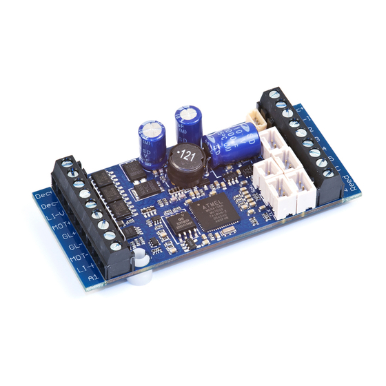
Illustration 10: Light and function output on bottom side In addition to the 3 light outputs, the eMOTION XLS Sound Decoder features 8 separate function outputs which may be used in different ways. Five outputs are located on the upper side as clamps, two additional outputs on a jack (F7/F8) and one on the rear side as solderable contact (F6). -
Page 42: Motor Control
MTS I or II requires a 14 speed step setting. This is the factory setting of the decoder. Several CV settings in the eMOTION XLS Sound Decoder influence the acceleration and deceleration characteristics of the locomotive. The acceleration/deceleration characteristic is defined by 2 CVs: Acceleration delay (CV3) •... - Page 43 The integrated load control works only with 24 kHz. The eMOTION XLS Sound Decoder is usable with all kinds of DC motors.
- Page 44 This means the decoder delivers more voltage to the motor(s) if the locomotive is running uphill in order to keep the speed constant. The eMOTION XLS Sound Decoder is equipped with a state-of-art integrated PI-Load Control (proportional-integral) that can be programmed efficiently by 3 CVs. These 3 CVs...
-
Page 45: Special Driving Functions
3.9.Analog mode In analog mode the eMOTION XLS Sound Decoder is fully functional with as little as 5V track voltage. The operation in analog mode may be de-activated with CV29–Bit2. The eMOTION XLS Sound Decoder features an internal motor characteristic curve which enables a smooth operation by measuring the track voltage. -
Page 46: The Sound In The Decoder
4.The Sound in the decoder The eMOTION XLS Sound Decoder contains a driving decoder as well as a full fledged digital power amplifier which reproduces all sounds and side noises of a locomotive in high quality and very realisticly. The eMOTION XLS Sound Decoder produces a locomotive’s prototypical operating sound as well as an array of additional... -
Page 47: Diesel Locomotive
The volume of each sound may be programmed separately in steps of four: 3 = max. volume 2 = ¾ 1 = ½ 0 = ¼ This value is set in CV201 for sound #1, in CV202 for sound #2, in CV203 for sound #3, etc. eMOTION XLS Sound Decoder... -
Page 48: Automatic Sounds
“255“ to activate the external volume control. 4.4.3. Loudspeaker specifications The power amplifier of the eMOTION XLS Sound Decoder delivers 1 Watt with a loudspeaker of 8 Ohms impedance. 8 Ohms impedance is a must for all loudspeakers used with the decoder to ensure proper... -
Page 49: Rpm Control, Control In- And Outputs
Track magnets may be utilized to trigger sounds (max. two). Two reed contacts must be connected to GND and potential-free to the respective input terminals of the eMOTION XLS sound decoder. The CVs 190 and 191 define the sounds to be triggered by the reed contacts. A very special function is the sound triggering depending on the driving direction. -
Page 50: Serial And Parallel Data Transfer
Three CVs are utilized to define the synchronization setting. 5.3.Reset functions In case the settings of your eMOTION XLS Sound Decoder are messed up or obscure, you may reset the decoder to the manufacturer’s settings by using specific CV values. A distinctive feature of the eMOTION XLS Sound Decoder is that you can reset a specific part of the decoder without changing the remaining parts. - Page 51 √ 1 ... 255 large value = strong Factor readjustment 61 PI-Load Control: Readjustment √ 1 ... 255 large value = slow readjustment Retardation 62 PI-Load Control: Readjustment Strength √ 1 ... 255 1 = fast limitation eMOTION XLS Sound Decoder...
- Page 52 0 ... 16 0=light, 1…16 = F-key 129 Lag time with power buffer, digital 2 ... 255 Only use Goldcap buffer operation 130 Lag time with power buffer, analog √ 2 ... 255 Only use Goldcap buffer operation eMOTION XLS Sound Decoder...
-
Page 53: Cv - Table (Sound Settings)
162 Add. Sound 12 : Number of Loops 0 ... 16 167 Control Register: Type of Sound read only (Do Not Change!!) 1=Steam, 2=Diesel, 6=Electric 168 Release Threshhold: Brake 0 ... 255 169 Trigger Threshhold: Brake 0 ... 255 eMOTION XLS Sound Decoder... - Page 54 196 Duration of a Steam Chuff 0 ... 32 0…32= duration of a steam chuff 198 Spacing Between Steam Chuff 0 ... 16 0…16 pause time between steam chuffs (only active if CV195 is set to "0") eMOTION XLS Sound Decoder...
-
Page 55: Sound Assignment
7.1.Sound assignment The settings for the sound in the eMOTION XLS Sound Decoder start at CV131. In this section specific sounds and noises may be assigned to desired F-keys. In addition a triggered sound may be looped for a prolonged play-back;... -
Page 56: Standing Sounds And Noises
7.6.Total volume level (CV200) and individual volume level (CV201 to CV212) The eMOTION XLS Sound Decoder features volume control by CV-programming. The volume of the sound may be changed by PoM programming at any time while operating a locomotive. In addition you may change the volume of each and every sound and noise individually. -
Page 57: Attachment 3: Switching Output Commands
CV 67 - 94 Curve 5 Short Address (CV1) Long Address (stored in CV17+18) 6 not used 7 not used 8.1.Attachment 2: (CV49) - Massoth-Configuration Off (Value=0) Application Value Note 0 Parallel Data Transfer Only Seriell + Parallel Data automatic detection of seriell/... - Page 58 CV116 (F4 with F3) CV120 (F6 with F5) Pulse simulation for the pulsed smoke generator (Only CV 114 Charging Control of Voltage Buffer in Programming only in CV116: buffer controlled by F4 Mode only in hardware <1.4 (green PCB) eMOTION XLS Sound Decoder...
-
Page 59: Attachment 7: Basic Values Of Freely Programmable Driving Curve
7 Not Used 9.Decoder programming + update The eMOTION XLS Sound Decoder supports all programming methods in accordance with the latest NMRA/DCC standards. Please note that not all of the DCC systems currently available can be programmed according to this standard. The manufacturer of your DCC system should give you in-depth information. -
Page 60: Reading Configuration Variables (Cvs)
The readout of CV parameters shall not be mistaken for a programming procedure. However, it is essential for checking the programmed settings. The eMOTION XLS Sound Decoder provides this function and the readout can be easily accomplished with a handheld controller. After inserting the requested CV No. the controller will display the value of the respective variable. -
Page 61: Warranty
We recommend to utilize the loco's power socket if available or the Massoth Rolling Road. The update procedure starts with an extensive test of the communication line. In case the update shuts down prematurely, a better contact must be provided. -
Page 62: Support
All other trademarks printed are registered trademarks as well. No parts of this work may be reproduced or transmitted in any form or by any means, electronic or mechanical, including photocopying and recording, or by any information storage or retrieval system without the prior written permission by Massoth Elektronik GmbH unless such copying is expressly permitted by federal copyright law. - Page 63 MASSOTH ELEKTRONIK UND ELEKTROMECHANIK GMBH Versionsübersicht von eMotion-Produkten / Version overview of eMotion products eMotion LS + XLS + XLS-P (diverse Artikelnummern) Version Stand / Änderungen Datum 1.Serie für Dampf- Diesel + E-Lok 15.12.06 Schneller Programmstart wegen Programmierfehlern bei div. Zentralen 09.01.07...
- Page 64 MASSOTH ELEKTRONIK UND ELEKTROMECHANIK GMBH Versionsübersicht von eMotion-Produkten / Version overview of eMotion products eMotion LS + XLS + XLS-P (Misc. item numbers) Version revision / changes date 1.series for Steam / Diesel / E-loco 12/15/06 Fast program start cause of programming error on misc. central stations...
Need help?
Do you have a question about the eMOTION XLS and is the answer not in the manual?
Questions and answers