Table of Contents
Advertisement
Quick Links
Advertisement
Table of Contents

Related Manuals for Massoth eMOTION XLS-Onboard


Summary of Contents for Massoth eMOTION XLS-Onboard
- Page 1 Anschlussanleitung Installation Manual eMOTION XLS-Onboard 82x6xxx...
-
Page 2: Table Of Contents
Inhaltsverzeichnis Table of Contents Information & Hinweise ....Information ........Lieferumfang ........Description ........Beschreibung (Funktionsumfang) ..Scope of Supply ........ Wichtige Hinweise ......Warning Notes ........Inbetriebnahme ......... Hook-Up ..........Einbauhinweise ......... Installation Notes ......Grundeinstellungen ......Basic factory default settings .... Motor-/Gleis-/Schalteranschluß... -
Page 3: Information
Information & Hinweise Information & Notes Wir gratulieren Ihnen zum Kauf Congratulations on your purchase dieses Massoth Sounddecoders. of this Massoth Sounddecoder. Diese Anschlussanleitung erklärt This manual explains the installa- den Anschluss des Decoders tion of this Decoder step by step. -
Page 4: Warning Notes
Vergewissern Sie sich Make sure the CVs of the function VOR Inbetriebnahme, dass die outputs are set to the appropriate Spannung für den angeschlosse- value before hooking up any lights nen Verbraucher richtig eingestellt or other accessories. Massoth... - Page 5 ist! cannot be responsible for any • Der Sounddecoder ist kein damage if this is disregarded. Spielzeug! Betreiben Sie ihn nicht • The Decoder is not a toy! Do not unbeaufsichtigt! Er ist nur für den operate it unattended. It is intend- Einsatz in Modelleisenbahnen vor- ed only for use in model railways.
-
Page 6: Hook-Up
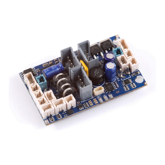
• Wenn nötig, zügig an den vorge- soldering iron! sehenen Stellen löten! Verwenden Sie einen kleinen Lötkolben! Inbetriebnahme Hook-Up 2.1 Einbauhinweise 2.1 Installation Notes Befestigen Sie den Decoder über The decoder is mounted with 3 die 3 vorgegebenen Bohrungen. screws. 2.2 Grundeinstellungen 2.2 Basic factory default settings Grundeinstellung... - Page 7 Licht / Light Steckdose Power socket FA2(-) Getriebe / Gearbox 1 Puffer Buffer Gleis Track Schalter / Getriebe / Gearbox 2 Switch Poti Reed Steckdose Power socket + + + - - - Takt / Clock 2 Takt / Clock 1 Licht / Light Unterseite / Bottom side FA4(-) Abbildung 1: eMOTION Decoder Anschlüsse...
-
Page 8: Motor / Track / Switch Connection
schalten, bzw. blinkt beim Fahren. while changing speed steps. 2.3 Motor-/Gleis-/Schalteranschluss 2.3 Motor / Track / Switch Connection Verbinden Sie Decoder und Getrie- Connect Decoder and gear be mit den vorhandenen Kabeln. box with the existing cables. Schließen Sie den Betriebsar- Connect the existing opera- tenschalter der Lokomotive an. - Page 9 Schalter LGB Betriebsartenschalter Switch LGB Operation Mode switch Gleis Gleisanschluss (Ausgang) Track Track Connection (Output) DEC- Gemeinsamer Anschluss (-) DEC- Common Terminal GND (-) (GND) Pol. für z.B. Puffer (GND) e. g. for a power buffer DEC+ Gemeinsamer Anschluss (+) DEC+ Common terminal (+) (+ 22V)
-
Page 10: Operation Mode Switch
Taktgeber 2 nur für Zahnrad- oder Clock 2 is designed for cog wheel Zweikraftloks. of dual engine locomotives. • Hinweis zu Poti: Bei Bedarf kann • Poti: The Poti connector connects hier eine externe Potentiometerpla- an external potentiometer for tine Art.Nr.: 8242010 angeschlos- manual volume control (item # sen werden. -
Page 11: Power Buffer (Bc)
A separate connector for power kann man einen Spannungspuffer buffers (#8151601 + #8151701). (8151601 + 8151701) anschlie- The power buffer bridges brief ßen. Massoth Powercaps besitzen power interruptions caused eine zusätzliche Steuerleitung, die by contaminated tracks or bad Störungen beim Einschalten oder power supply on switches. -
Page 12: Reed Contacts
The CV configura- Reedkontakte (potentialfrei) über tion (see Configuration Manual) die Reedkontaktanschlüsse des defines which sound is to be eMOTION XLS-Onboard Soundde- triggered by which reed contact. coders gegen GND angeschlossen (Illustr. #1) With the CV configura- werden (Abb. 1). -
Page 13: Technical Data
werden, um einen gepulsten synchronize a pulsed smoke with Verdampfer mit dem Sound zu the sound unit. synchronisieren. Technische Daten Technical Data • Spannungsversorgung • Power supply 0...24V DC/DCC (kurzz. bis 27V) 0...24V DC/DCC (max. peak 27V) • Gesamtbelastbarkeit • Maximum Load max. 4A max. -
Page 14: Warranty & Service
Gewährleistung & Kundendienst Warranty & Service MASSOTH gewährt die Fehlerfrei- MASSOTH warrants this product heit dieses Produkts im Rahmen against defects in materials and der gesetzlichen Vorgaben, workmanship for one year from mindestens jedoch für 1 Jahr ab the original date of purchase. Other Kaufdatum. -
Page 15: Hotline
We will be happy to answer your Rückfragen zu diesem Produkt zur questions about this product. Verfügung. Sie erreichen uns per You may reach us via eMail at: eMail unter: hotline@massoth.de hotline@massoth.de Die telefonische Hotline ist unter The phone hotline is available at +49 (0)6151-35077-38 +49 (0)6151-35077-38 zu bestimmten Zeiten geschaltet. - Page 16 Massoth Elektronik GmbH QUALITY Frankensteiner Str. 28 · D-64342 Seeheim · Germany MADE IN FON: +49 (0)6151-35077-0 · FAX: +49 (0)6151-35077-44 GERMANY eMail: info@massoth.de · www.massoth.de RoHS 032377o COMPLIANT 991092 BDA eMOTION XLS Onboard 2018.04...
Need help?
Do you have a question about the eMOTION XLS-Onboard and is the answer not in the manual?
Questions and answers