Table of Contents
Advertisement
Quick Links
Advertisement
Table of Contents

Subscribe to Our Youtube Channel
Related Manuals for Massoth eMOTION LS


Summary of Contents for Massoth eMOTION LS
- Page 1 LS Bedienungsanleitung eMOTION LS User Manual...
- Page 2 FREILANDTAUGLICHKEIT SUITABILITY FOR OUTDOOR USE Sehr geehrte Kunden, immer wieder errei- Dear customer, we have received a chen uns Anfragen bezüglich „rostender number of enquiries about rusty screws Schrauben“ bei Komponenten, die im in components that are used outside and Außenbereich der alljährlichen Witterung exposed to the elements.
-
Page 3: Table Of Contents
Sie sich VOR dem Anschluss der Lampen value before hooking up any lights or other und Funktionsausgänge das die Spannung accessories. Massoth cannot be responsible entsprechend der CV-Liste richtig eingestellt for any damage if this is disregarded. ist! Für Schäden durch Nichtbeachtung dieses Hinweises übernehmen wir keine... - Page 4 Wichtige Grundeinstellungen....Basic factory default settings....Programmierung........Programming........... Programmierspere CV 15/16....Programming Lock CV 15 / 16....Programmieradresse CV 107/108.... Programming Address CV 107 / 108..Lokadresse..........Locomotive address......... Anschluss und Funktion......Connections and functions....... Licht- und Funktionsausgänge....Light- and function outputs...... Automatic Uncoupler.......
-
Page 5: Summary Of Functions
Drehzahlregelung, Steuereingänge RPM control, control in- und Steuerausgang.......... and outputs..........Resetfunktion........... Reset functions......... Programmierung mittels PC und...... Programming via PC and Softwareupdate..........software update........Technische Daten..........Technical Data.......... Garantie, Reparatur, Kundendienst....Warranty, Service, Support....... Hotline.............. Hotline............1. Funktionsumfang 1. Summary of Functions •... - Page 6 (A6-8)) each (A6-8)) • Licht- und Funktionsausgänge • Light and function outputs may be dimmbar und analog aktivierbar dimmed + activated in analog mode • Programmierbare Blinklicht-, • Programmable blinking light, short- Impuls- und Taktgeberfunktion time function, and pulse generator •...
-
Page 7: Scope Of Supply
Funktionen kurzge- destroyed subsequently. schlossen, kann diese Sicherung To mount the eMOTION LS use our nicht wirken und der Decoder wird decoder bracket (# 8104010) zerstört. Zur Befestigung empfehlen Use a small soldering iron to prevent... -
Page 8: Motor And Track Connection
Fahrtrichtung links Gleis (+). left in direction of travel (LGB only)! Abbildung 1: Anschluss an Motor + Gleis Illustration 1: Installation of the eMOTION LS Sound Decoder Die angegeben Kabelfarben können The stated wire colors may differ vom Aufdruck am Getriebe abwei-... -
Page 9: Connection Of Speaker
Gleis + ge = Motor + Fahrtrichtung ws = Gleis + br = Gleis - gn = Motor - Gleis - Abbildung 2: Anschluss an ein LGB Getriebe Illustration 2: Installation on a LGB gear box 2.3 Lautsprecheranschluss 2.3 Connection of speaker An die Lautsprecher-Buchse wird The 8 Ohm loudspeaker is con- der 8 Ohm Lautsprecher ange-... -
Page 10: Advanced Settings
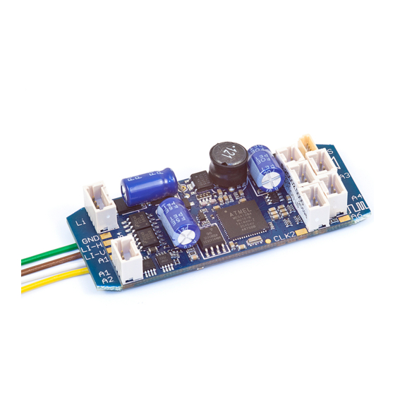
3. Erweiterte Einstellungen 3. Advanced settings 3.1 Anschlüsse auf der Oberseite 3.1 Terminals on the upper side Lautsprecher Speaker LI-V/LI-F Dec- Dec+ LI-I LI-H/LI-R Dec+ Dec- Dec- Dec- LI-H/LI-R Poti LI-V/LI-F Dec+ Dec- Dec+ Dec+ Dec- Taktgeber Takt/Clock Clock +6,5V Abbildung 4: eMOTION Decoder Anschlüsse Illustration #4: eMOTION contact assignment Dec-... - Page 11 CLK2 Connector for second pulse gen. CLK2 Anschluß für 2. Taktgeber The eMOTION LS Sound Decoder Auf der Oberseite des eMOTION LS features seven additional connectors Sounddecoders (Abb. 4) sind sieben on the upper side (illustration #4). zusätzliche Anschlussbuchsen • Clock: connector for an external vorhanden.
-
Page 12: Connectors On The Lower Surface
• Bus-Buchse: Der Busanschluss ist We suggest to use the micro vorgesehen zur Steuerung weiterer decoder cables (8312001, 8312002, Dec- Motor- Gleis- Gleis+ Reed 2 Motor+ Dec- Dec+ Reed 1 Abbildung 5: eMOTION Decoder Anschlüsse unten Illustration #5: eMOTION contact assignment lower surface Komponenten. - Page 13 Buffer Control (-) Buffer Control (-) Auf der Unterseite des eMOTION Some more contacts are located on LS Sounddecoders sind mehrere the lower side of the eMOTION LS Anschlüsse angebracht. Sound Decoder. • Getriebeanschlusskabel: Mit den 4 • Motor Cables: The LS Sound...
-
Page 14: Installation
• Reed 1 + 2: Dies sind Kontaktein- • Reed 1 + 2: These contacts can be gänge um z.B. Glocke oder Pfeife used to trigger the bell or whistle auszulösen, oder um eine einfache (programmable) or a simple shuttle Pendelfunktion zu realisieren. function. -
Page 15: Installation With Lgb Decoder Interface
Mit dem LGB Schnittstellenkabel Using the LGB decoder interface ® ® kann der Decoder zusätzlich an cable the eMOTION LS can be easily Loks mit der Decoderschnitt- installed in LGB locomotives with ® ® stelle eingebaut werden (Abb. a decoder interface (Illustr. #7). The 7). -
Page 16: Light And Function Outputs
Lötflächen. 4.4 Licht und Funktionsausgänge 4.4 Light and function outputs Der eMOTION LS verfügt über The eMOTION LS Sound Decoder fea- verschiedene Licht- und Funkti- tures 3 light outputs, front light, rear onsausgänge. Es befinden sich 3 light, and interior light. The front light Lichtanschlüsse auf dem Decoder. - Page 17 Unterseite des Decoders (A7, A8). 7+8 is 5Volts, and the maximum Alle Licht- und Funktionsausgänge allowable load is 10 mAmps. The A1-A4 des eMOTION LS Soundde- function (e.g. F-key assignment, light coders sind bei der Auslieferung display according to driving direction,...
-
Page 18: Power Buffer (Bc)
(not relevant for 128 speed steps) 4.5 Spannungspuffer (BC) 4.5 Power buffer (BC) Der eMOTION LS besitzt einen The eMOTION LS features a separate 3-poligen Lötanschluss für Span- connector for power buffers nungspuffer (8151601 + 8151701). (Massoth 8151601 + 8151701). -
Page 19: Reed Contacts To Trigger Bell And Whistle By Track Magnets
Reedkontakte magnets. The CV configuration (see (potentialfrei) über die Reedkontakt- Configuration Manual) defines which anschlüsse des eMOTION LS Sound- sound is to be triggered by which decoders gegen GND angeschlossen reed contact. (Illustr. #5) werden (Abb. 5). In der CV-Konfigu-... -
Page 20: Getting Started
5. Inbetriebnahme 5. Getting started Das Konzept des eMOTION LS legt eMOTION LS Decoders are designed großen Wert auf einfache Einbau- for easy handling and installation. To und Anschlussmöglichkeiten, daher make them fit into most of all types wird er mit abbrechbarer, beschrifte- of locomotives most of the Massoth ter Leiste ausgeliefert. - Page 21 Uncoupler (8414002). The Uncoupler vorbereitet. Der Entkuppler wird is connected directly to the sockets. direkt in die Anschlussbuchse gesteckt. Entkuppler Uncoupler Abbildung 10: Anschlüsse für Automatische Entkuppler am eMOTION LS Illustration #10: Connections for Automatic Uncoupler on the eMOTION LS...
- Page 22 6.3 Servofunktion 6.3 RC Servo function Ausgang 7 kann zur Steuerung eines Output 7 may be utilized to control an Servos genutzt werden. In CV 124 RC servo. This function is activated wird die Sondernutzung aktiviert. Mit with CV 124. CV 125 and CV 126 de- CV 125 + 126 wird der Drehbereich fine the turning range.
- Page 23 6.6 Busanschluss (CV 49) 6.6 Bus Connection • Massoth/LGB-Bus • Massoth/LGB bus Über den Massoth Bus bekommt der The Massoth bus provides the fol- LS Decoder folgende Informationen: lowing information: Acceleration, Anfahren, Anhalten und Lastzustand. stopping, load condition. • SUSI-Bus • SUSI bus Über den SUSI-Bus bekommt der...
- Page 24 9. Gewährleistung & Kundendienst 9. Warranty, Service, Support MASSOTH gewährt die Fehlerfreiheit MASSOTH warrants this product dieses Produkts im Rahmen der against defects in materials and gesetzlichen Vorgaben, mindestens workmanship for one year from jedoch für 1 Jahr ab Kaufdatum.
- Page 25 Return shipping Garantieanspruch. Der Anspruch auf charges are not covered by Serviceleistungen erlischt unwider- MASSOTH. Please include your proof ruflich. Verschleißteile sind von der of purchase with the returned goods. Garantieleistung ausgeschlossen. Please check our web site for up to...
- Page 28 Massoth Elektronik GmbH QUALITY Frankensteiner Str. 28 · D-64342 Seeheim · Germany MADE IN FON: +49 (0)6151-35077-0 · FAX: +49 (0)6151-35077-44 GERMANY eMail: info@massoth.de · www.massoth.de RoHS 032377o COMPLIANT 991031 BDA eMOTION LS 2019.03...
Need help?
Do you have a question about the eMOTION LS and is the answer not in the manual?
Questions and answers