
Related Manuals for Massoth eMOTION XL II


Summary of Contents for Massoth eMOTION XL II
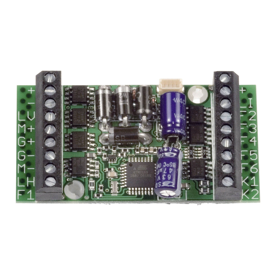
- Page 1 Konfigurationsanleitung Configuration Manual eMOTION XL II, XXL II Firmware Version 4.0...
-
Page 2: Table Of Contents
Inhaltsverzeichnis Table of Contents Einleitende Information ..... Introduction ........Wichtige Grundeinstellungen .... Basic factory default settings .... Inbetriebnahme ......... Getting started ........Programmierung ....... Programming ........Programmierung des Decoders ..Programming the Decoder ....Programmiersperre CV15/16 .... Programming Lock CV15/16 ..... Programmieren mit Fremdzentralen .. -
Page 3: Introduction
VOR dem Anschluss der Lampen und ing up any lights or other accessories. Funktionsausgänge das die Spannung Massoth cannot be responsible for entsprechend der CV-Liste richtig any damage if this is disregarded. eingestellt ist! Für Schäden durch Nichtbeachtung dieses Hinweises übernehmen wir keine Haftung. -
Page 4: Basic Factory Default Settings
Wichtige Grundeinstellungen Basic factory default settings Die Grundeinstellungen der ge- These are the factory defaults samten eMOTION Lokdecoderserie for some of the most frequently ist in der folgenden Tabelle darge- changed CVs. The CV table con- stellt. Den Funktionsumfang der tains the factory default settings einzelnen Decoder entnehmen Sie for all CVs. -
Page 5: Getting Started
To make them fit into keiten großen Wert, daher werden most of all types of locomotives viele Lokdecoder mit abbrechba- most of the Massoth eMOTION rer, beschrifteter Leiste ausgelie- decoders may be reduced in fert. Damit ist der Anschluss der size by detaching parts of the Lokdecoder besonders einfach. -
Page 6: Programming
It is essential to rekt gespeichert wurde. Wichtig ist switch off sounds or power buffers immer, dass zusätzliche Elektro- (without the Massoth control nikschaltungen wie Sound, Puffer cable) before programming the lo- (ohne Massoth Steuerkabel), etc. comotive. If a CV did not change to... -
Page 7: Programming Lock Cv15/16
CV 8 = Programmiersperre zurücksetzen. 16 to its factory default settings. STANDARDWERTE CV 15/16 STANDARD VALUE CV 15/16 133 = eMOTION XL II PluG 133 = eMOTION XL II PluG 135 = eMOTION XXL II 135 = eMOTION XXL II... - Page 8 3.3 Programmieren mit 3.3 Programming with other Fremdzentralen Central Stations Beachten Sie, dass nicht alle Please note that these standards genannten Programmiervarian- are not supported by all DCC ten von allen Digitalsystemen systems currently available. The unterstützt werden. Die Anleitung manufacturers documentation Ihres Digitalsystems sollte hier of your DCC system will give...
-
Page 9: Settings
Einstellungen Settings Es gibt einige CVs, die besonders Some CVs of special importance wichtig sind und richtig eingestellt require a correct setting for prop- sein sollten, damit ein einwand- per operation which are explained freier Betrieb sichergestellt ist. in the following chapter. Please Einige CVs werden hier kurz check the CV list for detailed facts. -
Page 10: Speed Curves
4.3 Fahrkurven 4.3 Speed curves Das Fahrverhalten kann mittels The speed characteristic of the Fahrkurve beeinflusst werden. locomotive is defined by the speed Wahlweise können eine lineare curve. You may choose between Fahrkurve oder eine frei program- a linear speed curve or a freely mierbare Fahrkurve verwendet programmable speed curve. - Page 11 bei mittlerer Geschwindigkeit the speed curve individually in langsamer, es ergibt sich ein 28 steps (CV 67 - CV 94). This ausgedehnter Langsamfahrbe- speed curve is activated by CV reich, optimal für Rangierfahrten. 29 bit 4. In this case the CVs 2, 5, and 6 are deactivated! Alternativ kann über CV 67 bis CV 94 die Fahrkurve in 28 Stufen...
-
Page 12: Switching Speed
4.4 Rangiergang 4.4 Switching Speed Für ein deutlich feineres Fahrgefühl The maximum speed is reduced beim Rangieren kann über eine by half to facilitate a more effective frei programmierbare Funktions- driving characteristic during switch- taste ein Rangiergang aktiviert ing. This feature may be set to any werden (CV 210). -
Page 13: Load Control
4.7 Lastregelung 4.7 Load Control Der Decoder besitzt eine Lastre- The load control may be set for op- gelung, die durch 3 CV‘s optimal timum operation by four CVs. The eingestellt werden kann. Im Auslie- factory default setting is set for fast ferungszustand ist diese Regelung control reaction. - Page 14 Steht der Wert zum Beispiel auf and the locomotive will slow 128 so wird die Nachregelung down when the load is increased. auf 50% begrenzt. Wird diese Load control may be switched Grenze erreicht, regelt der Dekoder off in CV 49 (Bit1, Value2). nicht noch weiter nach und die Lok wird unter großer Last etwas langsamer.
- Page 15 CV 49 abschaltbar (Bit1, Wert2). Illustration 2: Operating Modes of the PI-Load Control...
-
Page 16: Shuttle Function & Contact K1
4.8 Pendelfunktion & Kontakt K1 4.8 Shuttle function & Contact K1 Für automatische Abläufe kann For automatic functions a zwischen K1 und GND ein reed contact may be con- Reedkontakt geschaltet werden. nected to K1 and GND. • CV 214 Sperrzeit •... - Page 17 Schaltbefehle: Switch Command: AN/AUS: Normaler Schaltausgang ON/OFF: Regular switch function Deaktiviert: Ausgang ohne Funkt. Deactivated: w/o function Dauer-An: Immer „AN“ mit Funkt. Perman.-ON: always ON w. funct. Funktionen: Functions: • Paarweise Wechselfunktion • pairwise alternating function Wechselblinker, in Abhängigkeit alternating function in dependence mit vorhergehendem Ausgang of previous function output (z.B.
- Page 18 • Double strobe • Double strobe doppelter Lichtblitz, Sekundentakt double flash every second • Entkuppler • Uncoupler Anschluss für Massoth-Entkuppler connector for Massoth uncouplers Invertierung: Inversion: Funktion wird invertiert wenn aktiv If activated, function is inverted (nur bei Servobetrieb möglich) (only for servo operation)
-
Page 19: Servo Function
4.10 Servofunktion 4.10 Servo Function Die Ausgänge A7 + A8 können zur The outputs A7 + A8 may operate direkten Steuerung von Servos ge- servos directly. The servo end nutzt werden. Die Endwerte sind im points may be programmed is gültigen Servobereich frei program- required. -
Page 20: Buffer Operation
4.13 Pufferbetrieb (CV 47) 4.13 Buffer Operation (CV 47) Wird über „BC“ ein Pufferspei- If a power buffer is connected to cher betrieben, kann über CV 47 “BC”, CV 47 sets the buffering die Puffernachlaufzeit eingestellt time. Digital operation with a buffer werden. -
Page 21: Reset Function
Programmiersperre CV15/16 needs to be deactivated. CV15/CV16 aufgehoben sein. Gewährleistung & Kundendienst Warranty & Customer Service MASSOTH gewährt die Fehlerfrei- MASSOTH warrants this product heit dieses Produkts im Rahmen against defects in materials and der gesetzlichen Vorgaben, workmanship for one year from mindestens jedoch für 1 Jahr ab... -
Page 22: Hotline
Fremdeingriff oder it directly to the manufacturer. Veränderung des Produkts besteht Return shipping charges are not kein Gewährleistungsansprich. covered by MASSOTH. Please Der Anspruch auf Serviceleis- include your proof of purchase tungen erlischt unwiderruflich. with the returned goods. - Page 24 Zeitfunktion asym. kurz Zeitfunktion asym. lang Monoflop Einschaltverzögerung Kesselfeuer TV flackern Fotograf/Blitzlicht Petroleum flackern Leuchtstoffröhre Start Marslight Single Strobe Double Strobe/Graylight Servofunktion Fahrstufen-Servo MASSOTH Entkuppler Taktgeber Auf-/Abdimmen PWM-Regelung Inverser Ausgang Z: Zeitwert erforderlich, D: Dimmen möglich, *: In Kombination mit dimmbaren Funktionen...
- Page 25 Petroleum flickering Flourescent tube Marslight Single strobe Double Strobe servo function servo speed step control MASSOTH Uncoupler Clock (Hall Sensor) Fade In / Out Dimming (PWM) Inverted function T: time period required, D: Dimming available; *: In combination with dimmable functions...
- Page 26 CV - Tabelle - Standardeinstellungen. (S = Standard, A = Analogbetrieb) Konfigurationsvariablen (CV-Tabelle) CV Beschreibung A Bereich Bemerkung Lokadresse (standard kurz) 1...127 wenn CV 29, Bit 5 = 0 Anfahrspannung 1...255 CV2 x (1/255 Gleisspannung) Anfahrverzögerung √ 1...255 CV3 x 2ms x (1/255 Gleissp.) Bremsverzögerung 10 √...
-
Page 27: Cv Tables
CV - Table - Standard settings of the 8FS-decoder. (D = Default, A = analog operation) Table of configuration variables (CV table) CV Description Range Note Loco address (standard short) 1...127 if CV 29 bit 5 = 0 Starting voltage 1...255 CV 2 x (1/255 track voltage) Acceleration time √... - Page 28 Fahrkurve programm. Fahrkurve (CV 67-94) Bit 5 kurze Lokadresse (CV 1) lange Lokadresse (CV 17/18) 47 Puffernachlaufzeit √ 1...250 1Sek. pro Wert 49 MASSOTH Konfiguration 18 √ bitweise Programmierung Wert AUS (Wert 0) Bit 1 Digitale Lastregelung = AUS Digitale Lastregelung...
- Page 29 Bit 5 short address (CV 1) long address (CV 17/18) 47 Buffer runtime √ 1...250 1sec per value 49 MASSOTH Configuration 18 √ bitwise programming Wert OFF (Value 0) Bit 1 Digital Load Control = OFF Digitale Lastregelung...
- Page 30 Konfigurationsvariablen (CV-Tabelle) CV Beschreibung A Bereich Bemerkung 111 A1: Schaltbefehlszuordnung B siehe Anhang 1 112 A1: Dimmwert 100 √ siehe Anhang 2 113 A1: Bedingungen √ siehe Anhang 3 115 A1: Sonderfunktion √ siehe Anhang 4 116 A1: Zeitwert für Sonderfunktion 10 √...
- Page 31 Table of configuration variables (CV table) CV Description Range Note 111 A1: Command allocation B see attachment 1 112 A1: Dimming 100 √ see attachment 2 113 A1: Condition √ see attachment 3 115 A1: Special function √ see attachment 4 116 A1: time period for special function 10 √...
- Page 32 Konfigurationsvariablen (CV-Tabelle) CV Beschreibung A Bereich Bemerkung 160 A6: Schaltbefehlszuordnung A siehe Anhang 1 161 A6: Schaltbefehlszuordnung B siehe Anhang 1 162 A6: Dimmwert 100 √ 1...100 siehe Anhang 2 163 A6: Bedingungen √ siehe Anhang 3 165 A6: Sonderfunktion √ siehe Anhang 4 166 A6: Zeitwert für Sonderfunktion 10 √...
- Page 33 Table of configuration variables (CV table) CV Description Range Note 160 A6: Command allocation A see attachment 1 161 A1: Command allocation B see attachment 1 162 A6: Dimming 100 √ 1...100 see attachment 2 163 A6: Condition √ see attachment 3 165 A6: Special function √...
- Page 34 227 Servo 2: Drehgeschwindigkeit 10 √ 1...250 2ms pro Wert und Stufe 255 Decodertyp-Kennung (Standardwerte nur lesbar für Programmiersperre CV 15/16) 133 = eMOTION XL II PluG 135 = eMOTION XXL II Anhang 1: Schaltbefehle Wert Verwendung Bemerkung 0 = Schalten mit der Lichttaste 0 - 28 1 ...
- Page 35 227 Servo 2: rotation speed 10 √ 1...250 2ms per value and step 255 Decoder type (standard values for read only programming lock CV 15/16) 133 = eMOTION XL II PLuG 135 = eMOTIOn XXL II Attachment 1: Command allocation A Value Application Note...
- Page 36 Anhang 2: Dimmwerte + Servofunktion Wert Verwendung Bemerkung Feste Werte für Sonderfunktionen Servofunktion Standard Servofunktion Standard mit Endabschaltung Servo (standard) mit Fahrstufen Servo (standard) mit Fahrstufen und Endabschaltung Nur A7 / A8 Inv. Servo (standard) Inv. Servo (standard) mit Endabschaltung Inv.
- Page 37 Anhang 2: Dimming values + Servo function Value Application Note Fixed values for special features standard servo function standard servo function with end position switch off standard servo with speed step operation standard servo with speed step and end position switch off A7 / A8 only inverted standard servo function inverted standard servo function...
- Page 38 Anhang 4: Sonderfunktionen Wert Verwendung Bemerkung Blinken asymetrisch kurz AN (1:4) Zeitwert (0,1s/Wert) bestimmt den längeren Wert Blinken asymetrisch lang AN (4:1) Fotoblitz Zeitwert angeben Kurzzeitfunktion, Monoflop (Zeitbasis 0,1s/Wert) Ausgang wird nach Zeitablauf automatisch abgeschaltet Einschaltverzögerung Kesselfeuersimulation Nur an A4, A5 TV-Simulation Nur an A3 Petroleumlampe Zufallsflackern...
- Page 39 Attachment 4: Special function Value Application Note flash asymetric short on (1:4) time period (0.1s/value) defines the long value flash asymetric long on (4:1) Photographer flash time period required Monoflop (time basis 0,1sec per value) output deactivates after preset time Switch-ON delay Fire box A4, A5 only...
- Page 40 Anhang 5: CV-Werte bei Decoder-Resetfunktion Wert 170 171 172 173 175 176 180 181 182 183 185 190 191 192 193 30 121 30 121 30 100 195 196 200 201 202 203 205 206 220 221 222 225 226 227 30 100 62 210 212 214 215 10 200 50...
- Page 41 Attachment 5: Default settings at resets Value 170 171 172 173 175 176 180 181 182 183 185 190 191 192 193 30 121 30 121 30 100 195 196 200 201 202 203 205 206 220 221 222 225 226 227 30 100 62 210 212 214 215 10 200 50...
- Page 44 Massoth Elektronik GmbH QUALITY Frankensteiner Str. 28 · D-64342 Seeheim · Germany MADE IN FON: +49 (0)6151-35077-0 · FAX: +49 (0)6151-35077-44 GERMANY eMail: info@massoth.de · www.massoth.de RoHS COMPLIANT 991094 BDA eMOTION DEC II CONF 2016.07...
Need help?
Do you have a question about the eMOTION XL II and is the answer not in the manual?
Questions and answers