
Related Manuals for Supermicro SC745BTQ-R1K28B


Summary of Contents for Supermicro SC745BTQ-R1K28B
- Page 1 UPER ® SC745 CHASSIS Series SC745BTQ-R1K28B SC745BTQ-R1K28B-SQ SC745TQ-(R)1200B SC745TQ-(R)920B SC745TQ-(R)800B USER’S MANUAL 1.0b...
- Page 2 This product, including software and documentation, is the property of Supermicro and/or its licensors, and is supplied only under a license. Any use or reproduction of this product is not allowed, except as expressly permitted by the terms of said license.
- Page 3 SC745 4U chassis. Installa- tion and maintenance should be performed by experienced technicians only. Supermicro's SC745 chassis series is optimized for the latest Intel® Xeon® proces- sor and is also compatible with previous generation Intel and AMD dual processor- based motherboards.
- Page 4 SC745 Chassis Manual Manual Organization Chapter 1: Introduction The first chapter provides a checklist of the main components included with this chassis and describes the main features of the SC745 chassis. This chapter also includes contact information. Chapter 2: System Safety This chapter lists warnings, precautions, and system safety.
- Page 5 Preface Appendix A: Chassis Cables Appendix B: Power Supply Specifications Appendix C: SAS-743TQ Backplane Manual...
-
Page 6: Table Of Contents
Chassis Features ................1-2 CPU ....................1-2 Hard Drives ..................1-2 I/O Expansion slots ................1-2 Peripheral Drives ................1-2 Other Features ..................1-2 Contacting Supermicro ..............1-3 Chapter 2 Standardized Warning Statements for AC/DC Systems ..................2-1 About Standardized Warning Statements ........2-1 Warning Definition ................2-1 Installation Instructions ..............2-4 Circuit Breaker ...................2-5... - Page 7 Preface Fans ....................3-2 Mounting Rails (optional)..............3-2 Power Supply ..................3-2 Air Shroud ..................3-2 Where to get Replacement Components ........3-2 Chapter 4 System Interface ............4-1 Overview ...................4-1 Control Panel Buttons ..............4-2 Control Panel LEDs .................4-2 Drive Carrier LEDs ................4-4 SAS/SATA Drives ................4-4 Chapter 5 Chassis Setup and Maintenance .......5-1 Overview ...................5-1 Installation Procedures ..............5-1...
- Page 8 SC745 Chassis Manual Rack Precautions ................6-2 General Server Precautions ..............6-2 Rack Mounting Considerations .............. Ambient Operating Temperature ............Reduced Airflow ................. Mechanical Loading ................Circuit Overloading ................Reliable Ground ................. Rack Mounting Considerations ............6-3 Ambient Operating Temperature ........... 6-3 Reduced Airflow ................6-3 Mechanical Loading ..............6-3 Circuit Overloading ................6-3 Reliable Ground ................6-3...
-
Page 9: Chapter 1 Introduction
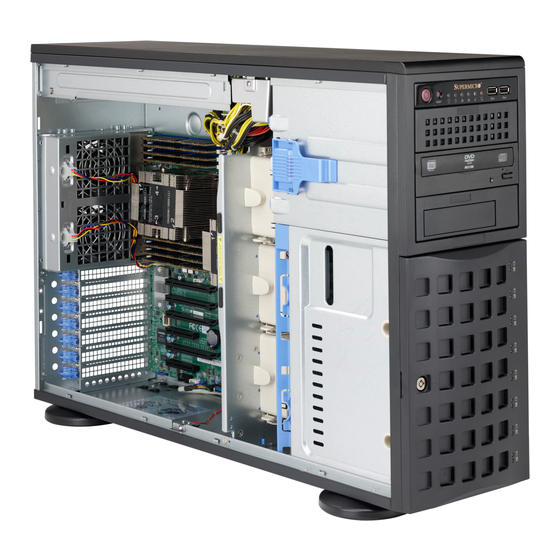
Chapter 1 Introduction Overview Supermicro’s SC745 4U chassis features a unique and highly-optimized design. The chassis is equipped with high efficiency power supply. High-performance fans provide ample optimized cooling for the system and eight hot-swappable drive bays offer maximum storage capacity in a 4U form factor. -
Page 10: Chassis Features
SC745 Chassis Manual Chassis Features The SC745 4U high-performance chassis includes the following features: Hard Drives The SC745 chassis features eight slots for SAS/SATA drives. These drives are hot-swappable. Once set up correctly, these drives can be removed without power- ing down the server. -
Page 11: Contacting Supermicro
Super Micro Computer, Inc. 980 Rock Ave. San Jose, CA 95131 U.S.A. Tel: +1 (408) 503-8000 Fax: +1 (408) 503-8008 Email: marketing@supermicro.com (General Information) support@supermicro.com (Technical Support) Website: www.supermicro.com Europe Address: Super Micro Computer B.V. Het Sterrenbeeld 28, 5215 ML... - Page 12 SC745 Chassis Manual Notes...
-
Page 13: Chapter 2 Standardized Warning Statements For Ac/Dc Systems
Only certified technicians should attempt to install or configure components. Read this appendix in its entirety before installing or configuring components in the Supermicro chassis. These warnings may also be found on our web site at http://www.supermicro.com/ about/policies/safety_information.cfm. Warning Definition Warning! This warning symbol means danger. - Page 14 SC745 Chassis Manual Warnung WICHTIGE SICHERHEITSHINWEISE Dieses Warnsymbol bedeutet Gefahr. Sie befinden sich in einer Situation, die zu Verletzungen führen kann. Machen Sie sich vor der Arbeit mit Geräten mit den Gefahren elektrischer Schaltungen und den üblichen Verfahren zur Vorbeugung vor Unfällen vertraut.
- Page 15 Warning Statements for AC Systems جسذٌة اصابة ًتتسبب ف حالة ٌوكي أى ًاًك ف خطز ًٌٌع هذا الزهز !تحذٌز الذوائز بالوخاطز الٌاجوة عي ي على علن ، ك هعذات تعول على أي قبل أى الكهزبائٍة حىادث أي وقىع وٌع ل الىقائٍة...
-
Page 16: Installation Instructions
SC745 Chassis Manual Installation Instructions Warning! Read the installation instructions before connecting the system to the power source. 設置手順書 システムを電源に接続する前に、 設置手順書をお読み下さい。 警告 将此系统连接电源前,请先阅读安装说明。 警告 將系統與電源連接前,請先閱讀安裝說明。 Warnung Vor dem Anschließen des Systems an die Stromquelle die Installationsanweisungen lesen. ¡Advertencia! Lea las instrucciones de instalación antes de conectar el sistema a la red de alimentación. -
Page 17: Circuit Breaker
Chapter 2: Warning Statements for AC/DC Systems Circuit Breaker Warning! This product relies on the building's installation for short-circuit (overcurrent) protection. Ensure that the protective device is rated not greater than: 60VDC, 20 A. サーキッ ト ・ ブレーカー この製品は、 短絡 (過電流) 保護装置がある建物での設置を前提としています。 保護装置の定格が60VDC、... -
Page 18: Power Disconnection Warning
SC745 Chassis Manual 경고! 이 제품은 전원의 단락(과전류)방지에 대해서 전적으로 건물의 관련 설비에 의존합니다. 보호장치의 정격이 반드시 60V(볼트), 20A(암페어)를 초과하지 않도록 해야 합니다. Waarschuwing Dit product is afhankelijk van de kortsluitbeveiliging (overspanning) van uw electrische installatie. Controleer of het beveiligde aparaat niet groter gedimensioneerd is dan 60V, 20A. - Page 19 Chapter 2: Warning Statements for AC/DC Systems ¡Advertencia! El sistema debe ser disconnected de todas las fuentes de energía y del cable eléctrico quitado de los módulos de fuente de alimentación antes de tener acceso el interior del chasis para instalar o para quitar componentes de sistema. Attention Le système doit être débranché...
-
Page 20: Equipment Installation
SC745 Chassis Manual Equipment Installation Warning! Only trained and qualified personnel should be allowed to install, replace, or service this equipment. 機器の設置 トレーニングを受け認定された人だけがこの装置の設置、 交換、 またはサービスを許可 されています。 警告 只有经过培训且具有资格的人员才能进行此设备的安装、更换和维修。 警告 只有經過受訓且具資格人員才可安裝、更換與維修此設備。 Warnung Das Installieren, Ersetzen oder Bedienen dieser Ausrüstung sollte nur geschultem, qualifiziertem Personal gestattet werden. -
Page 21: Restricted Area
Chapter 2: Warning Statements for AC/DC Systems Waarschuwing Deze apparatuur mag alleen worden geïnstalleerd, vervangen of hersteld door geschoold en gekwalificeerd personeel. Restricted Area Warning! This unit is intended for installation in restricted access areas. A restricted access area can be accessed only through the use of a special tool, lock and key, or other means of security. -
Page 22: Battery Handling
SC745 Chassis Manual אזור עם גישה מוגבלת !אזהרה יש להתקין את היחידה באזורים שיש בהם הגבלת גישה. הגישה ניתנת בעזרת .)'כלי אבטחה בלבד (מפתח, מנעול וכד محظورة مناطق ٍنتركُبها ف هذه انىحذة تخصيص تم ،أداة خاصت من خالل استخذاو فقط محظورة... - Page 23 Chapter 2: Warning Statements for AC/DC Systems Warnung Bei Einsetzen einer falschen Batterie besteht Explosionsgefahr. Ersetzen Sie die Batterie nur durch den gleichen oder vom Hersteller empfohlenen Batterietyp. Entsorgen Sie die benutzten Batterien nach den Anweisungen des Herstellers. Attention Danger d'explosion si la pile n'est pas remplacée correctement. Ne la remplacer que par une pile de type semblable ou équivalent, recommandée par le fabricant.
-
Page 24: Redundant Power Supplies
SC745 Chassis Manual Redundant Power Supplies Warning! This unit might have more than one power supply connection. All connections must be removed to de-energize the unit. 冗長電源装置 このユニッ トは複数の電源装置が接続されている場合があります。 ユニッ トの電源を切るためには、 すべての接続を取り外さなければなりません。 警告 此部件连接的电源可能不止一个,必须将所有电源断开才能停止给该部件供电。 警告 此裝置連接的電源可能不只一個,必須切斷所有電源才能停止對該裝置的供電。 Warnung Dieses Gerät kann mehr als eine Stromzufuhr haben. Um sicherzustellen, dass der Einheit kein trom zugeführt wird, müssen alle Verbindungen entfernt werden. -
Page 25: Backplane Voltage
Chapter 2: Warning Statements for AC/DC Systems امداد الطاقة بوحدات عدة اتصاالت جهاز ال يكون لهذا قد الكهرباء عن وحدة ال لعسل كافة االتصاالت يجب إزالة 경고! 이 장치에는 한 개 이상의 전원 공급 단자가 연결되어 있을 수 있습니다. 이 장치에 전원을... -
Page 26: Comply With Local And National Electrical Codes
SC745 Chassis Manual מתח בפנל האחורי !הרה אז קיימת סכנת מתח בפנל האחורי בזמן תפעול המערכת. יש להיזהר במהלך .העבודה اللىحة أوالطاقة المىجىدة على التيار الكهزبائي مه خطز هناك هذا الجهاس خدمة كه حذرا عند يعمل النظام عندما يكىن 경고! 시스템이... -
Page 27: Product Disposal
Chapter 2: Warning Statements for AC/DC Systems Attention L'équipement doit être installé conformément aux normes électriques nationales et locales. תיאום חוקי החשמל הארצי !אזהרה הציוד חייבת להיות תואמת לחוקי החשמל המקומיים והארציים התקנת المتعلقة المحلية والىطىية قىاويه يجب أن يمتثل لل الكهربائية... -
Page 28: Hot Swap Fan Warning
SC745 Chassis Manual ¡Advertencia! Al deshacerse por completo de este producto debe seguir todas las leyes y reglamentos nacionales. Attention La mise au rebut ou le recyclage de ce produit sont généralement soumis à des lois et/ou directives de respect de l'environnement. Renseignez-vous auprès de l'organisme compétent. - Page 29 Chapter 2: Warning Statements for AC/DC Systems 警告 當您從機架移除風扇裝置,風扇可能仍在轉動。小心不要將手指、螺絲起子和其他 物品太靠近風扇。 Warnung Die Lüfter drehen sich u. U. noch, wenn die Lüfterbaugruppe aus dem Chassis genommen wird. Halten Sie Finger, Schraubendreher und andere Gegenstände von den Öffnungen des Lüftergehäuses entfernt. ¡Advertencia! Los ventiladores podran dar vuelta cuando usted quite ell montaje del ventilador del chasis.
-
Page 30: Dc Power Supply
SC745 Chassis Manual DC Power Supply Warning! When stranded wiring is required, use approved wiring terminations, such as closedloop or spade-type with upturned lugs. These terminations should be the appropriate size for the wires and should clamp both the insulation and conductor. 警告... - Page 31 Chapter 2: Warning Statements for AC/DC Systems Attention Quand des fils torsadés sont nécessaires, utiliser des douilles terminales homologuées telles que celles à circuit fermé ou du type à plage ouverte avec cosses rebroussées. Ces douilles terminales doivent être de la taille qui convient aux fils et doivent être refermées sur la gaine isolante et sur le conducteur.
-
Page 32: Dc Power Disconnection
SC745 Chassis Manual DC Power Disconnection Warning! Before performing any of the following procedures, ensure that power is removed from the DC circuit. 警告 次の手順を開始する前に、 DC回路から電源が切断されているこ とを確認してく ださい。 警告 進行以下任一操作程序前,請確保直流電路已斷電。 警告 请在进行以下任一操作程序前,确保直流电路的电源已经断开。 Warnung Vor Ausführung der folgenden Vorgänge ist sicherzustellen, daß die Gleichstromschaltung keinen Strom erhält. -
Page 33: Hazardous Voltage Or Energy Present On Dc Power Terminals
Chapter 2: Warning Statements for AC/DC Systems 주의! 다음 절차들을 수행하기 전에, 전원이 DC회로로부터 제거되었는지를 확인해 주십시오. Waarshuwing Wanneer geslagen bedrading vereist is, dient u bedrading te gebruiken die voorzien is van goedgekeurde aansluitingspunten, zoals het gesloten-lus type of het grijperschop type waarbij de aansluitpunten omhoog wijzen. - Page 34 SC745 Chassis Manual ¡Advertencia! Puede haber energía o voltaje peligrosos en los terminales eléctricos de CC. Reemplace siempre la cubierta cuando no estén utilizándose los terminales. Asegúrese de que no haya acceso a conductores descubiertos cuando la cubierta esté colocada. Attention Le voltage ou l'énergie électrique des terminaux à...
-
Page 35: Chapter 3 Chassis Components
SC745 models come in black. Backplane Each SC745 chassis comes with a 4U backplane. For more information regarding compatible SAS/SATA backplanes, view the appendices found at the end of this manual. Additional information can be found on our website at www.supermicro.com. -
Page 36: Fans
Supermicro Authorized Distributors/System Integrators/Resellers. A list of Supermicro Authorized Distributors/System Integra- tors/Reseller can be found at www.supermicro.com. Click the Where to Buy link. -
Page 37: Chapter 4 System Interface
Chapter 4: System Interface Chapter 4 System Interface Overview There are several LEDs on the control panel as well as others on the drive carriers to keep you constantly informed of the overall status of the system, as well as the activity and health of specific components. -
Page 38: Control Panel Buttons
SC745 Chassis Manual Control Panel Buttons There are two push-buttons located on the front of the chassis. These are the power on/off button and the reset button. Power: The main power switch is used to apply or remove power from the power supply to the server system. - Page 39 Chapter 4: System Interface NIC2: Indicates network activity on GLAN2 when flashing. NIC1: Indicates network activity on GLAN1 when flashing. HDD: Indicates SAS/SATA drive activity when flashing. Power: Indicates power is being supplied to the system's power supply units. This LED should normally be illuminated when the system is operating.
-
Page 40: Drive Carrier Leds
SC745 Chassis Manual Drive Carrier LEDs Your chassis uses SAS/SATA drives. SAS/SATA Drives Each SAS/SATA drive carrier has two LEDs. • Green: Each SAS/SATA drive carrier has a green LED. When illuminated, this green LED (on the front of the SAS/SATA drive carrier) indicates drive activity. A connection to the SATA backplane enables this LED to blink on and off when that particular drive is being accessed. -
Page 41: Chapter 5 Chassis Setup And Maintenance
Chapter 5: Chassis Setup and Maintenance Chapter 5 Chassis Setup and Maintenance Overview This chapter covers the steps required to install components and perform mainte- nance on the chassis. The only tool you will need to install components and perform maintenance is a Phillips screwdriver. -
Page 42: Removing The Chassis Front And Side Covers
SC745 Chassis Manual Removing the Chassis Front and Side Covers Side Cover Cover Latch Button Cover Latch Handle Figure 5-1: Removing the Chassis Cover The Side Cover Removing the Chassis Side Cover 1. Power down the system and remove the power cords from the rear of the power supplies. -
Page 43: The Front Cover
Chapter 5: Chassis Setup and Maintenance Front Cover Front Cover Lock Figure 5-2: Opening the Front Cover The Front Cover The front cover houses up to eight hot-swappable hard drives. The cover can be locked to prevent unauthorized access. The key to this lock is shipped with the system. -
Page 44: Configuring The Storage Module
SC745 Chassis Manual Configuring the Storage Module Storage Module Figure 5-3: Chassis in Tower Mode Storage Module Figure 5-4: Chassis in Rack Mount Mode Tower or Rack Configuration The SC745 chassis is shipped in tower mode and can be immediately used as desktop server. - Page 45 Chapter 5: Chassis Setup and Maintenance Storage Module Storage Module Release Lever Figure 5-5: Remove the Storage Module Rotating the Storage Module for Rack Mounting 1. Power down the system and remove the power cords from the rear of the power supplies.
- Page 46 B. Add up to three peripheral drives (CD-ROM, DVD-ROM, etc.) drive trays. C. Add five hot swappable hard drives to the storage module. This configuration requires a M35 mobile rack. More information on mobile racks can be found at the Supermicro Website at www.supermicro.com...
- Page 47 Chapter 5: Chassis Setup and Maintenance Drive Tray Release Tabs Figure 5-7: Remove Drive Tray Adding up to Three Peripheral/Hard Drives to the Drive Trays 1. Power down the system and remove the power cords from the rear of the power supplies.
- Page 48 SC745 Chassis Manual Peripheral Drive Tray Hard Drive Figure 5-8: Add a Hard Drive to the Peripheral Drive Tray 4. Place the drive into the drive tray. If installing a hard drive, make sure the type of hard drive (SAS/SATA) is supported by the motherboard. 5.
- Page 49 Chapter 5: Chassis Setup and Maintenance Peripheral Drive Tray Release Tabs Figure 5-9: Remove Peripheral Drive Tray Up to three peripheral drives (DVD-ROM, CD-ROM and others) may be added to the peripheral drive trays. Adding up to Three Peripheral Drives to the Drive Trays 1.
- Page 50 SC745 Chassis Manual Peripheral Drive Tray Peripheral Tray Rails Figure 5-10: Add Peripheral Tray Rails to the DVD-ROM Drive 4. Remove the peripheral tray rails from the peripheral drive tray. To do this, you must remove two screws from each side. 5.
- Page 51 The SC745 chassis accepts an M35TQ mobile rack to install extra hot-swappable hard drives. The mobile rack goes into the storage module which goes into the chassis. For more information on mobile racks, visit the Supermicro Web site at www. supermicro.com. Adding Five Hard Drives Using A Supermicro Mobile Rack 1.
- Page 52 SC745 Chassis Manual Peripheral Tray Rails Peripheral Drive Tray Figure 5-12: Remove the Peripheral Tray Rails 4. Remove the peripheral tray rails from the peripheral tray. To do this, you must remove two screws from each side. Do this for all three peripheral trays. 5.
-
Page 53: Installing Hard Drives
Chapter 5: Chassis Setup and Maintenance Installing Hard Drives Drive Tray Handle Release Button Figure 5-14: Install Hard Drives The drives are mounted in drive carriers to simplify their installation and removal from the chassis. These carriers also help promote proper airflow for the drive bays. - Page 54 SC745 Chassis Manual Drive Tray SAS/SATA Hard Drive Figure 5-15: Remove Dummy Drive Tray 4. Remove the screws holding the drive tray to the dummy drive. 5. Place a hard drive in the drive tray. Figure 5-16: Install Hard Drive 6.
-
Page 55: Installing The Motherboard
Chapter 5: Chassis Setup and Maintenance Installing the Motherboard I/O Shield The I/O shield holds the motherboard I/O ports in place. Install the I/O shield before you install the motherboard. MB I/O Shield Figure 5-17: SC745 Chassis MB I/O Shield Installation Installing the I/O Shield: 1. -
Page 56: Permanent And Optional Standoffs
SC745 Chassis Manual Permanent and Optional Standoffs Standoffs prevent short circuits by securing space between the motherboard and the chassis surface. The SC745 chassis packaging includes optional standoffs (hexagonal-shaped posts). These standoffs accept the rounded Phillips head screws which are also included in the SC745 accessories package. Standoffs Figure 5-18: Chassis Standoffs 5-16... -
Page 57: Installing The Motherboard
Chapter 5: Chassis Setup and Maintenance Installing the Motherboard Motherboard Installation 1. Review the documentation that came with your motherboard. Become familiar with component placement, requirements, and precautions. 2. Power down the system and remove the power cords from the rear of the power supplies. - Page 58 SC745 Chassis Manual Power Supply Connections Connect each of the following cables as required by your motherboard manufac- turer. In some instances not all of these cables are required, and some cables may not be included. Power Supply Cable Name Connects to Description 20-pin or 24-pin power cable pro-...
-
Page 59: Expansion Card And Pci Slot Setup
Chapter 5: Chassis Setup and Maintenance Lift the Press the Middle Release Tab of the Release Tab Figure 5-19: Add-on Card/Expansion Card Port Expansion Card and PCI Slot Setup After the motherboard has been installed, expansion cards may be installed. Installing Expansion Cards 1. - Page 60 SC745 Chassis Manual Figure 5-20: Remove PCI Card Slot Guard 5. Remove the screw holding the bracket in place and pull the bracket from the chassis. 6. Install your PCI card or other add-on card into the PCI slot bracket and moth- erboard.
-
Page 61: Installing The Air Shroud
Chapter 5: Chassis Setup and Maintenance Installing the Air Shroud Removable Tabs Figure 5-21: Air Shroud Air shrouds concentrate airflow to maximize fan efficiency. The SC745 chassis air shroud does not require screws to set up. NOTE: The air shroud includes tabs that can be removed if motherboard compo- nents prevent the air shroud from fitting securely. -
Page 62: Installation Complete
SC745 Chassis Manual Air Shroud Figure 5-22: Air Shroud in Place Checking the Airflow 1. Make sure there are no objects to obstruct airflow in and out of the server. 2. Do not operate the server without drives or drive trays in the drive bays. Use only recommended server parts. -
Page 63: System Fans
Chapter 5: Chassis Setup and Maintenance System Fans Five heavy-duty fans provide cooling for the chassis. Three fans are located in the front of the chassis with two fans in the rear. These fans circulate air through the chassis as a means of lowering the internal temperature of the chassis. The fans come pre-installed to the chassis. - Page 64 SC745 Chassis Manual Rear Fan Release Tab Figure 5-24: Rear Chassis Fans Replacing a Rear Chassis Fan 1. Press the rear fan release tab. 2. Pull the fan from the chassis top first. 3. Place the new fan in the chassis bottom first. 4.
-
Page 65: Power Supply
Chapter 5: Chassis Setup and Maintenance Power Supply Depending on your chassis model, the SC745 chassis has an 800, 920, 1200 or 1280 Watt power supply. "R" model chassis feature a second redundant power sup- ply. This power supply is auto-switching capable. This enables it to automatically sense and operate at a 100v to 240v input voltage. - Page 66 SC745 Chassis Manual Notes 5-26...
-
Page 67: Chapter 6 Rack Installation
Chapter 6: Rack Installation Chapter 6 Rack Installation Overview This chapter provides a quick setup checklist to get your chassis up and running. Following these steps in the order given should enable you to have the system operational within a minimum amount of time. Unpacking the System You should inspect the box the chassis was shipped in and note if it was damaged in any way. -
Page 68: Rack Precautions
SC745 Chassis Manual Rack Precautions • Ensure that the leveling jacks on the bottom of the rack are fully extended to the floor with the full weight of the rack resting on them. • In single rack installation, stabilizers should be attached to the rack. •... -
Page 69: Rack Mounting Considerations
Chapter 6: Rack Installation Rack Mounting Considerations Ambient Operating Temperature If installed in a closed or multi-unit rack assembly, the ambient operating temperature of the rack environment may be greater than the ambient room temperature. There- fore, consideration should be given to installing the equipment in an environment compatible with the manufacturer’s maximum rated ambient temperature (TMRA). -
Page 70: Rack Mounting Instructions
SC745 Chassis Manual Rack Mounting Instructions This section provides information on installing the SC745 chassis into a rack unit with the optional rail. There are a variety of rack units on the market, which may mean the assembly procedure will differ slightly. You should also refer to the instal- lation instructions that came with the rack unit you are using. - Page 71 Chapter 6: Rack Installation Removing the Top Cover 1. Power down the system and remove the power cords from the rear of the power supplies. Open the chassis cover as described in Section 5-3. 2. Locate the chassis cover lock (blue lever) at the rear of the chassis cover. 3.
-
Page 72: Identifying The Sections Of The Rack Rails
SC745 Chassis Manual Identifying the Sections of the Rack Rails The chassis package includes two rack rail assemblies in the rack mounting kit. Each assembly consists of two sections: an inner fixed chassis rail that secures directly to the server chassis and an outer fixed rack rail that secures directly to the rack itself. - Page 73 Chapter 6: Rack Installation Figure 6-3: Installing the Inner Rack Rails Installing the Chassis Handles and Inner Rails 1. Locate the two chassis handles and six handle screws. 2. Align the chassis handle with the front of the chassis and secure with the three chassis handle screws.
- Page 74 SC745 Chassis Manual Secure to the Rear of the Rack Attach to Middle Section Secure to the Front of the Rack Figure 6-4: Assembling the Outer Rails Installing the Outer Rails onto the Rack 1. Attach the front and rear short brackets to the outside of the long bracket. Both bracket ends must face the same direction.
- Page 75 Chapter 6: Rack Installation Figure 6-5: Installing the Chassis into a Rack Note: figures are for illustrative purposes only. Always install servers into racks from the bottom up. Fro m Subject Siz e Rec eived Ro d Coleman Ray mond Miller RE: SC825 C hassis User M anual 4 KB F...
-
Page 76: Tower Mounting Instructions
SC745 Chassis Manual Tower Mounting Instructions The SC745 chassis is shipped with the chassis cover and feet pre-installed. To use the chassis as a desktop server, no other installation is required. Use the instructions in this section if you have converted the chassis for rack use and need to return the chassis to tower mounting. - Page 77 Chapter 6: Rack Installation Chassis Foot Receptacle Chassis Foot Chassis Screw Figure 6-7: Placing Chassis Feet Placing the Chassis Feet 1. Place the chassis foot in the foot receptacle and slide the foot toward the front of the chassis. The foot should lock into place. 2.
- Page 78 SC745 Chassis Manual Notes 6-12...
-
Page 79: Appendix A Sc745 Chassis Cables
This appendix lists supported cables for your chassis system. It only includes the most commonly used components and configurations. For more compatible cables, refer to the manufacturer of the motherboard you are using and our Web site at: www.supermicro.com. A-2 Cables Included with SC745TQ Chassis (SAS/SATA) Part #... - Page 80 SC745 Chassis Manual A-4 Compatible Cables The following cables are compatible with the SC745 chassis. Some compatible motherboards have different connectors. If your motherboard has only one SAS connector that the SAS/SATA cables must share, use the following cable. This cable must be purchased separately. Cable Name: SAS Cable Quantity: 1 Part #: CBL-0288L...
- Page 81 Appendix A: Chassis Cables Extending Power Cables Although Supermicro chassis are designed with to be efficient and cost-effective, some compatible motherboards have power connectors located in different areas. To use these motherboards you may have to extend the power cables to the mother boards.
- Page 82 SC745 Chassis Manual Notes...
-
Page 83: Appendix B Sc745 Power Supply Specifications
Appendix B: Power Supply Specifications Appendix B SC745 Power Supply Specifications This appendix lists power supply specifications for your chassis system. 800W (Redundant = X2) MFR Part # PWS-801-1R 100 - 240V Rated AC Voltage 50 - 60Hz 10 - 4 Amp +5V standby 4 Amp +12V... - Page 84 SC745 Chassis Manual 1200W (Redundant = X2) MFR Part # PWS-1K21P-1R 100 - 140V, 50 - 60Hz, 8 - 11.5 Amp Rated AC Voltage 180 - 240V, 50 - 60Hz, 5.5 - 8 Amp 1000W, 83 Amp @ 100-140V DC Output +12V 1200W, 100 Amp @ 180-240V 5Vsb: 4A +5V: 50 Amp...
-
Page 85: Appendix C Bpn-Sas-743Tq Backplane Specifications
Appendix C: BPN-SAS-743TQ Backplane Specifications Appendix C BPN-SAS-743TQ Backplane Specifications To avoid personal injury and property damage, carefully follow all the safety steps listed below when accessing your system or handling the components. C-1 ESD Safety Guidelines Electrostatic Discharge (ESD) can damage electronic com ponents. To prevent dam- age to your system, it is important to handle it very carefully. - Page 86 This manual reflects SAS-743TQ Revision 3.00, the most current release available at the time of publication. Always refer to the Supermicro website at www.super- micro.com for the latest updates, compatible parts and supported configurations.
- Page 87 Appendix C: BPN-SAS-743TQ Backplane Specifications C-5 Front Connectors Figure C-1: Front Connectors 1. JTAG Connector: JP47 10. SAS Port #0 J5 2. Upgrade Connector: JP46 11. SAS Port #1 J6 3. Chip: MG9072 12. SAS Port #2 J7 4. Power Connectors (4-pin): JP10, 13.
- Page 88 SC745 Chassis Manual Front Connector and Pin Definitions #1. and #2. JTAG Connector and Upgrade Connectors The JTAG and Upgrade connectors, des- ignated JP47 and JP46, are used for diag- nostic purposes. These connectors should be used by a certified and experienced technician.
- Page 89 Appendix C: BPN-SAS-743TQ Backplane Specifications #6. and #7. Sideband Headers Sideband Headers The sideband headers are designated JP51 Pin # Definition Pin # Definition and JP52. For SES-2 to work properly, you Backplane Controller must connect an 10-pin sideband cable. Addressing ID (SB6) (SB5)
- Page 90 SC745 Chassis Manual Front Jumper Locations and Pin Definitions JP50 JP38 JP40 JP41 JP33 JP34 JP36 JP37 JP29 JP18 JP43 JP42 Figure C-2: Front Jumpers...
- Page 91 Appendix C: BPN-SAS-743TQ Backplane Specifications Explanation of Jumpers Connector To modify the operation of the backplane, Pins jumpers can be used to choose between optional settings. Jumpers create shorts between two pins to change the function Jumper of the connector. Pin 1 is identified with a square solder pad on the printed circuit board.
- Page 92 SC745 Chassis Manual C and SGPIO Mode Jumper Settings This backplane can utilize I C or SGPIO. I C is the default mode and can be used without making changes to your jumpers. The following information details which jumpers must be configured to use SGPIO mode or restore your backplane to I mode.
- Page 93 Appendix C: BPN-SAS-743TQ Backplane Specifications Front LED Indicators OH/Drive Fail LED Figure C-3: Front LEDs Front Panel LEDs State Specification Overheat/drive failure LED indicator (Red light: flashing, Buzzer: On, if activated)
- Page 94 SC745 Chassis Manual Rear Connectors and LED Indicators SAS #0 SAS #1 SAS #2 SAS #3 SAS #4 SAS #5 SAS #6 SAS #7 Figure C-4: Rear Connectors Rear SAS/SATA Connectors Rear Connector SAS Drive Number SAS #0 SAS/SATA HHD #0 SAS #1 SAS/SATA HHD #1 SAS #2...
- Page 95 Appendix C: BPN-SAS-743TQ Backplane Specifications Notes C-11...
- Page 96 SC745 Chassis Manual Disclaimer (cont.) The products sold by Supermicro are not intended for and will not be used in life sup- port systems, medical equipment, nuclear facilities or systems, aircraft, aircraft devices, aircraft/emergency communication devices or other critical systems whose failure to per- form be reasonably expected to result in significant injury or loss of life or catastrophic property damage.
Need help?
Do you have a question about the SC745BTQ-R1K28B and is the answer not in the manual?
Questions and answers