
Related Manuals for Supermicro Supero SC732 Series


Summary of Contents for Supermicro Supero SC732 Series
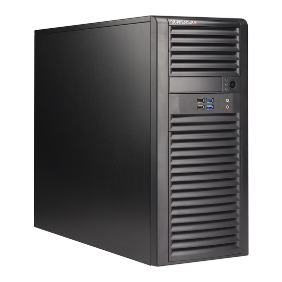
- Page 1 UPER ® SC732 CHASSIS SERIES SC732D SC732i SC732D4F-500B SC732D4F-865B SC732D4-500B SC732D4-865B SC732D2-500B SC732D2-865B SC732i-500B SC732i-865B USER’S MANUAL 1.0a...
- Page 2 This product, including software and documentation, is the property of Supermicro and/or its licensors, and is supplied only under a license. Any use or reproduction of this product is not allowed, except as expressly permitted by the terms of said license.
- Page 3 SC732 chassis. Installation and maintenance should be performed by experienced technicians only. Supermicro’s SC732 chassis features a unique and highly optimized design, al- lowing the user to install components with minimal or no use of screws or tools.
-
Page 4: Manual Organization
SC732 Chassis Manual Manual Organization Chapter 1 Introduction The first chapter provides a description of the main components included with this chassis and describes the main features of the SC732 chassis. This chapter also includes contact information. Chapter 2 System Safety This section lists warnings, precautions, and system safety. -
Page 5: Table Of Contents
Table of Contents Chapter 1 Introduction Overview ......................1-1 Where to get Replacement Components ............1-1 Shipping Lists ....................1-1 Contacting Supermicro ..................1-3 Returning Merchandise for Service..............1-4 Chapter 2 System Safety Overview ......................2-1 Warnings and Precautions ................2-1 Preparing for Setup .................. - Page 6 SC732 Chassis Manual Notes...
-
Page 7: Chapter 1 Introduction
Chapter 1 Introduction Overview Supermicro’s SC732 chassis features a unique and highly-optimized design, allow- ing most configuration of the chassis to be accomplished without tools or screws. The chassis is equipped with a high-efficiency power supply and high-performance fans provide ample optimized cooling for the FB-DIMM memory modules. Four 3.5"... - Page 8 SC732 Chassis Manual PWS-865-PQ Power Model I/O Slots Supply SC732D4F-865B 4x 3.5" 865W SC732D4-865B 2x 5.25" 7x FF high- DP/UP SC732D2-865B (Optional) efficiency SC732i-865B PWS-502-PQ Power Model I/O Slots Supply 4x 3.5" 500W SC732D4F-500B SC732D4-500B 2x 5.25" 7x FF high- DP/UP SC732D2-500B (Optional)
-
Page 9: Contacting Supermicro
Super Micro Computer, Inc. 980 Rock Ave. San Jose, CA 95131 U.S.A. Tel: +1 (408) 503-8000 Fax: +1 (408) 503-8008 Email: marketing@supermicro.com (General Information) support@supermicro.com (Technical Support) Web Site: www.supermicro.com Europe Address: Super Micro Computer B.V. Het Sterrenbeeld 28, 5215 ML... -
Page 10: Returning Merchandise For Service
For faster service, RMA authorizations may be requested online (http://www.super- micro.com/support/rma/). Whenever possible, repack the chassis in the original Supermicro carton, using the original packaging material. If these are no longer available, be sure to pack the chassis securely, using packaging material to surround the chassis so that it does not shift within the carton and become damaged during shipping. -
Page 11: Chapter 2 System Safety
Chapter 2: System Safety Chapter 2 System Safety Overview This chapter provides a quick setup checklist to get your chassis up and running. Following the steps in the order given should enable you to have your chassis set up and operational within a minimal amount of time. This quick setup assumes that you are an experienced technician, famailiar with common concepts and terminology. - Page 12 SC732 Chassis Manual down the server with the operating system and then unplug the power cords from all the power supply modules in the system. • When working around exposed electrical circuits, another person who is fa- miliar with the power-off controls should be nearby to switch off the power, if necessary.
-
Page 13: General Safety Precautions
Chapter 2: System Safety General Safety Precautions • Keep the area around the chassis clean and free of clutter. • Place the chassis top cover and any system components that have been re- moved away from the system or on a table so that they won’t accidentally be stepped on. - Page 14 SC732 Chassis Manual • Handle a board by its edges only; do not touch its components, peripheral chips, memory modules or contacts. • When handling chips or modules, avoid touching their pins. • Put the serverboard and peripherals back into their antistatic bags when not in use.
-
Page 15: Chapter 3 System Interface
Chapter 3 System Interface Chapter 3 System Interface Overview There are several LEDs on the control panel as well as others on the drive carriers to keep you constantly informed of the overall status of the system as well as the activity and health of specific components. - Page 16 SC732 Chassis Manual NIC LED HDD LED OH LED Power Button Audio 2x IEEE 1394a 2x USB 2.0 2x USB 3.0 SC732D4F NIC LED HDD LED OH LED Power Button Audio 2x USB2.0 2x USB 3.0 SC732D4 NIC LED HDD LED OH LED Power Button...
-
Page 17: Control Panel Buttons
Chapter 3 System Interface Control Panel Buttons Power: The main power button is used to apply or remove power from the power supply to the system. When the power is on, the power button will be lighted by a blue LED. Turning off the system power with this button will cause the blue LED to turn off and will remove the main power, but will keep standby power supplied to the system. - Page 18 SC732 Chassis Manual SC732D2 model chassis: • Two USB 2.0 ports • One audio port • One microphone port SC732i model chassis: • Two USB 2.0 ports...
-
Page 19: Control Panel Leds
Chapter 3 System Interface Control Panel LEDs The control panel located on the front of the SC732 chassis has three LEDs. These LEDs provide you with critical information related to different parts of the system. This section explains what each LED indicates when illuminated and any corrective action you may need to take. - Page 20 SC732 Chassis Manual Notes...
-
Page 21: Chapter 4 Chassis Setup And Maintenance
Chapter 4: Chassis Setup and Maintenance Chapter 4 Chassis Setup and Maintenance Overview This chapter covers the steps required to install components and perform main- tenance on the chassis. Most components of the SC732 do not require tools or screws to set them up. Those components which must be secured with screws require only a Phillips screwdriver. -
Page 22: Removing The Chassis Side Covers
SC732 Chassis Manual Removing the Chassis Side Covers Figure 4-1: Removing the Chassis Side Covers The SC732 features two removable side covers, allowing easy access to the chas- sis interior. Removing the Side Covers Disconnect the chassis from any power souce. Remove the two screws securing the left side cover to the chassis. -
Page 23: Rotating The Hard Drive Cage
Chapter 4: Chassis Setup and Maintenance Rotating the Hard Drive Cage Release Tab (A) HDD Cage (B) Figure 4-2: Rotating the Hard Drive Cage In order to access and install components in the chassis interior, it is necessary to rotate the hard drive cage (B). This will provide sufficient room to install and configure the chassis components. -
Page 24: Removing And Installing 3.5" Hard Drives
SC732 Chassis Manual Removing and Installing 3.5" Hard Drives Release Tabs Figure 4-3: Removing the Hard Drive Carrier from the Hard Drive Cage The SC732 chassis must be powered-down before hard drives can be removed from the hard drive carriers. Removing and Installing 3.5"... - Page 25 Chapter 4: Chassis Setup and Maintenance Figure 4-4: Removing the 3.5" Hard Drive from the Hard Drive Carrier If a hard drive is already present, remove it by carefully pulling the sides of the hard drive carrier outward. Remove the hard drive from the hard drive carrier. Warning: Only enterprise level HDDs are recommended for use in this chassis.
- Page 26 SC732 Chassis Manual Optional Screw Figure 4-5: Installing the Hard Drive Carrier into the Hard Drive Cage Insert the new hard drive into the hard drive carrier. Insert the hard drive carrier into the hard drive cage, sliding it towards the back of the the hard drive cage until it clicks into a locked position.
-
Page 27: Removing And Installing 2.5" Hard Drives (Optional)
Chapter 4: Chassis Setup and Maintenance Removing and Installing 2.5" Hard Drives (Optional) Thumb Screw Figure 4-6: Removing the 2.5" Hard Drives The SC732 chassis must be powered-down before hard drives can be removed from the hard drive carriers. Removing and Installing 2.5" Hard Drives Disconnect the chassis from any power source. - Page 28 SC732 Chassis Manual Figure 4-7: Installing 2.5" Hard Drives If a hard drive is already present, remove it by carefully pulling the sides of the hard drive carrier outward. Remove the hard drive from the hard drive carrier. Insert the new hard drive into the hard drive carrier. Insert the hard drive carrier into the hard drive cage, sliding it towards the back of the the hard drive cage until it clicks into a locked position.
-
Page 29: Installing The I/O Shield And Motherboard
Chapter 4: Chassis Setup and Maintenance Installing the I/O Shield and Motherboard I/O Shield Figure 4-8: I/O Shield Placement I/O Shield An I/O shield holds the motherboard ports in place. Install the I/O shield before you install the motherboard. The maximum size of motherboard supported by the SC732 is a 12"... -
Page 30: Motherboard Installation
SC732 Chassis Manual Motherboard Installation Installing the Motherboard Review the documentation that came with your motherboard. Become familiar with component placement, requirements, precautions, and cable connec- tions. Disconnect the chassis from any power source. Rotate the hard drive cage 90 degrees outward, as described in the previous section, Rotating the Hard Drive Cage. -
Page 31: Installing A 3.5" Device (Optional)
Chapter 4: Chassis Setup and Maintenance Installing a 3.5" Device (Optional) The SC732D chassis has one 3.5" device slot, which supports an optional device, such as an all-in-one card reader. Installing a 3.5" Device Remove the front bezel from the chassis by lifting it upwards from the bottom, and pulling off the front of the chassis. -
Page 32: Installing Expansion Cards
SC732 Chassis Manual Installing Expansion Cards Protective Bracket (B) Release Latch (A) PCI Card Slots Figure 4-11: Locating Expansion Card Components Expansion Card and PCI Slot Setup The SC732 chassis includes seven PCI card slots for expansion cards. The number of cards used varies, depending upon the motherboard models. -
Page 33: Full-Height, Full-Length Expansion Card Setup
Chapter 4: Chassis Setup and Maintenance Full-Height, Full-Length Card Holders (A) Figure 4-12: Installing a Full-Height, Full-Length Expansion Card Full-Height, Full-Length Expansion Card Setup The SC732 chassis includes clips to accomodate the use of full-height, full-length expansion cards. These clips support and stabilize the cards, preventing them from contacting any undesired surfaces. -
Page 34: Installing The System Fans
SC732 Chassis Manual Installing the System Fans Figure 4-13: Installing the Rear Exhaust Fan Installing the Rear Exhaust Fan Disconnect all power to the chassis. Insert the four rubber pins through mounting holes in the rear of the chassis and through the mounting holes in the rear fan. Pull the rubber pins through the mounting holes of the fan to secure the fan to the chassis. - Page 35 Chapter 4: Chassis Setup and Maintenance Figure 4-14: Installing the Front Cooling Fan (Optional) Installing the Front Cooling Fan (Optional) Disconnect all power to the chassis. Insert the four rubber pins through the front fan bracket and into the mounting holes in the front fan.
-
Page 36: 4-10 Installing The Front Bezel
SC732 Chassis Manual 4-10 Installing the Front Bezel Front Bezel Installation Insert the tabs on the front bezel into the mounting holse on the front of the chassis. Ensure that the cover fits snugly. This completes the installation of basic components in the SC732 chassis Figure 4-15: Installing the Front Bezel 4-16... -
Page 37: 4-11 Power Supply
Chapter 4: Chassis Setup and Maintenance 4-11 Power Supply The SC732 chassis includes either a 500 Watt or a 865 Watt power supply. In the unlikely event that it becomes necessary to replace the power supply, follow the instructions below. Power Supply Figure 4-16: Removing the Power Supply Changing the Power Supply... - Page 38 SC732 Chassis Manual Notes 4-18...
-
Page 39: Appendix A Cables, Screws, And Other Accessories
This appendix lists the supported cables for the SC732 chassis. It only includes the most commonly used components and configurations. For more compatible cables, refer to the manufacturer of the motherboard and our Web site at: www. supermicro.com. A-2 Cables Included with SC732 Chassis SC732D4F, SC732D4, SC732D2... - Page 40 SC732 Chassis Manual A-3 Chassis Screws The accessory box includes all the screws needed to set up your chassis. This section lists and describes the most commonly used screws. Your chassis may not require all of the parts listed. HARD DRIVE Flat head Pan head 6-32 x 5 mm...
-
Page 41: Appendix B Sc732 Power Supply Specifications
Appendix B: Power Supply Specifications Appendix B SC732 Power Supply Specifications This appendix lists power supply specifications for your chassis system. SC732D4F-500B, SC732D4-500B, SC732D2-500B, SC732i-500B 500W MFR Part # PWS-502-PQ 100 - 240V Rated AC Voltage 50 - 60Hz 12 - 6 Amp +5V standby 6.5 Amp +12V 69 Amp +5V 30 Amp... - Page 42 SC732 Chassis Manual Disclaimer (cont.) The products sold by Supermicro are not intended for and will not be used in life sup- port systems, medical equipment, nuclear facilities or systems, aircraft, aircraft devices, aircraft/emergency communication devices or other critical systems whose failure to per- form be reasonably expected to result in significant injury or loss of life or catastrophic property damage.
Need help?
Do you have a question about the Supero SC732 Series and is the answer not in the manual?
Questions and answers