Page 1
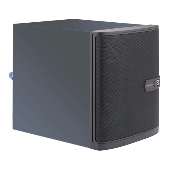
SC721 CHASSIS SERIES SC721TQ-250B USER’S MANUAL 1.0a...
Page 2
This product, including software and documentation, is the property of Supermicro and/or its licensors, and is supplied only under a This manual is written for professional system integrators and PC technicians. It license.
Overview ......................1-1 Chapter 3 Chassis Components Shipping Lists ....................1-1 Contacting Supermicro ..................1-2 See this chapter for information on the components included with your system. Returning Merchandise for Service..............1-3 Chapter 2 Standardized Warning Statements for AC Systems Chapter 4 System Interface About Standardized Warning Statements ............
Page 4
SC721 Chassis Manual Chapter 3 Chassis Components Components ....................3-1 Drive Bays ....................... 3-1 Motherboard Support ..................3-1 Power Supply ....................3-1 Fans ........................ 3-1 PCI Slots ......................3-1 Control Panel Buttons and LED Indicators ............. 3-2 Unpacking the System ..................3-2 Where to Get Replacement Components ............
Page 5
Chapter 1 Introduction Overview Supermicro’s SC721 chassis features a unique and highly-optimized design, allow- ing most configuration of the chassis to be accomplished without tools or screws. The chassis is equipped with high-efficiency power supply. A high-performance fan provides ample optimized cooling for FB-DIMM memory modules, and four hot-swap drive bays offer maximum storage capacity (Default Design for 84W TDP CPU).
Website: www.supermicro.com Whenever possible, repack the chassis in the original Supermicro carton, using the original packaging material. If these are no longer available, be sure to pack the Europe chassis securely, using packaging material to surround the chassis so that it does Address: Super Micro Computer B.V.
The following statements are industry standard warnings, provided to warn the user of situations which have the potential for bodily injury. Should you have questions or experience difficulty, contact Supermicro's Technical Support department for assistance. Only certified technicians should attempt to install or configure components.
Page 9
SC721 Chassis Manual Warning Statements for AC Systems Warnung WICHTIGE SICHERHEITSHINWEISE Dieses Warnsymbol bedeutet Gefahr. Sie befinden sich in einer Situation, die zu Verletzungen führen kann. Machen Sie sich vor der Arbeit mit Geräten mit den Gefahren elektrischer Schaltungen und den üblichen Verfahren zur Vorbeugung vor Unfällen vertraut.
SC721 Chassis Manual Chapter 2: Warning Statements for AC Systems Installation Instructions Circuit Breaker Warning! Warning! This product relies on the building's installation for short-circuit (overcurrent) Read the installation instructions before connecting the system to the power source. protection. Ensure that the protective device is rated not greater than: 250 V, 20 A. 設置手順書...
SC721 Chassis Manual Chapter 2: Warning Statements for AC Systems ¡Advertencia! 경고! El sistema debe ser disconnected de todas las fuentes de energía y del cable 이 제품은 전원의 단락(과전류)방지에 대해서 전적으로 건물의 관련 설비에 eléctrico quitado de los módulos de fuente de alimentación antes de tener acceso 의존합니다.
SC721 Chassis Manual Chapter 2: Warning Statements for AC Systems Equipment Installation Waarschuwing Deze apparatuur mag alleen worden geïnstalleerd, vervangen of hersteld door Warning! geschoold en gekwalificeerd personeel. Only trained and qualified personnel should be allowed to install, replace, or service Restricted Area this equipment.
SC721 Chassis Manual Chapter 2: Warning Statements for AC Systems Warnung Bei Einsetzen einer falschen Batterie besteht Explosionsgefahr. Ersetzen Sie die Batterie nur durch den gleichen oder vom Hersteller empfohlenen Batterietyp. Entsorgen Sie die benutzten Batterien nach den Anweisungen des Herstellers. Attention Danger d'explosion si la pile n'est pas remplacée correctement.
SC721 Chassis Manual Chapter 2: Warning Statements for AC Systems Redundant Power Supplies 경고! Warning! This unit might have more than one power supply connection. All connections must 이 장치에는 한 개 이상의 전원 공급 단자가 연결되어 있을 수 있습니다. 이 장치에 be removed to de-energize the unit.
SC721 Chassis Manual Chapter 2: Warning Statements for AC Systems Attention L'équipement doit être installé conformément aux normes électriques nationales et locales. 경고! 경고! 시스템이 동작 중일 때 후면판 (Backplane)에는 위험한 전압이나 에너지가 발생 현 지역 및 국가의 전기 규정에 따라 장비를 설치해야 합니다. 합니다.
SC721 Chassis Manual Chapter 2: Warning Statements for AC Systems Warnung Attention Gefährlich Bewegende Teile. Von den bewegenden Lüfterblätter fern halten. La mise au rebut ou le recyclage de ce produit sont généralement soumis à des Die Lüfter drehen sich u. U. noch, wenn die Lüfterbaugruppe aus dem Chassis lois et/ou directives de respect de l'environnement.
UL ou CSA câbles certifiés qui ont UL ou CSA indiqué sur le code power cables and AC adaptors. Using any other cables and adaptors could cause pour tous les autres appareils électriques que les produits désignés par Supermicro a malfunction or a fire. Electrical Appliance and Material Safety Law prohibits the seulement.
Chapter 3: Components Chapter 3 Chassis Components This chapter describes some common components included with your chassis. For the latest information and shipping lists, visit http://www.supermicro.com. Components Drive Bays The SC721 chassis supports the drives below: • Four hot-swappable 3.5" hard drives.
Infrequently, you may need replacement parts for your system. To ensure the highest level of professional service and technical support, we recommend purchasing ex- clusively from our Supermicro Authorized Distributors/System Integrators/Resellers. A list of Supermicro Authorized Distributors/System Integrators/Resellers can be found at: http://www.supermicro.com. Click the Where to Buy link.
Chapter 4 System Interface Chapter 4 System Interface Overview The SC721 chassis includes a control panel which is located on the front of the chassis, behind the front bezel. This panel features power buttons and status moni- toring lights. These elements are described in this chapter with possible responses that you may need to take.
SC721 Chassis Manual Chapter 4 System Interface Control Panel Buttons Power Button NIC1 LED The main power switch is used to apply or remove power from the power supply Indicates network activity when flashing. to the server system. Turning off system power with this button removes the main power, but keeps standby power supplied to the system.
Chapter 5: Chassis Setup and Maintenance Chapter 5 Chassis Setup and Maintenance Overview This chapter covers the steps required to install components and perform main- tenance on the chassis. Most components of the SC721 do not require tools or screws to set them up. Those components which must be secured with screws require only a Phillips screwdriver.
SC721 Chassis Manual Chapter 5: Chassis Setup and Maintenance Removing the Chassis Cover Removing and Installing Hard Drives Figure 5-1. Removing the Chassis Cover Removing the Chassis Side Cover 1. Power down the system and unplug the power cord from the power supply as described in Section 5-2.
Page 26
SC721 Chassis Manual Chapter 5: Chassis Setup and Maintenance Hard Drive Dummy Drive Hard Drive Carrier Figure 5-3. Installing a Hard Drive into Hard Drive Carrier Figure 5-4. Installing the Hard Drive Carrier into the Hard Drive Cage Installing a Hard Drive into the Hard Drive Carrier 1.
SC721 Chassis Manual Chapter 5: Chassis Setup and Maintenance Installing the Internal Fixed Hard Drives Installing the Side Mounted Fixed Hard Drive The SC721 supports two internal 2.5" SATA fixed hard drives, one top mounted drive and one side mounted drive. Figure 5-6.
SC721 Chassis Manual Chapter 5: Chassis Setup and Maintenance Installing the I/O Shield and Motherboard Installing the Motherboard and I/O Shield 1. With the illustrations facing the outside of the chassis, insert the motherboard The SC721 supports a wide range of Mini-ITX motherboards, which are sold sepa- ports through the openings in the I/O shield.
SC721 Chassis Manual Chapter 5: Chassis Setup and Maintenance Hardware Security Kensington Cable Slot (K-Slot) The SC721 chassis features a Kensington cable slot or K-slot. This slot accepts a The SC721 features multiple locking devices to help deter hardware theft and pro- standard Kensington cable locking device (not included), Attach the loop end of the tect user data.
SC721 Chassis Manual Chapter 5: Chassis Setup and Maintenance Installing the DVD-ROM Drive Secure the DVD-ROM The SC721 chassis supports one DVD-ROM drive. Drive with Screws (Optional) Figure 5-13. Configuring the Chassis for the DVD-ROM Drive Figure 5-15. Installing the DVD-ROM Drive Installing the DVD-ROM Drive 1.
SC721 Chassis Manual Chapter 5: Chassis Setup and Maintenance 5-10 Installing Expansion Cards 5-11 Installing the Rear Exhaust Fan The SC721 chassis includes one PCI slot for an expansion card. Figure 5-17. Installing the Exhaust Fan The SC721 includes a 12 cm rear exhaust fan that provides cooling for the chassis. The chassis features a set of mounting holes which will support a standard 9 cm exhaust fan (fan not included).
SC721 Chassis Manual Chapter 5: Chassis Setup and Maintenance 5-12 Replacing the Power Supply 5-13 Replacing the Backplane The SC721 chassis includes a 250 Watt power fixed supply. In the unlikely event The SC721 chassis includes a BPN-SAS-733TQ backplane. In the unlikely event that it becomes necessary to replace the power supply, follow the instructions below.
Appendix A: Power Supply Specifications Appendix A Power Supply Specifications This appendix lists power supply specifications for your chassis system. The SC721 chassis includes a power supply rated at 80 Plus Bronze Level. SC721TQ-250B 250W MFR Part # PWS-251-1H AC Voltage 100 - 240V, 50 - 60Hz, 5 Amp +5V Max:14 Amp;...
Appendix B: BPN-SAS3-733TQ Backplane Specifications Appendix B BPN-SAS-733TQ Backplane Specifications To avoid personal injury and property damage, carefully follow all the safety steps listed below when accessing your system or handling the components. B-1 ESD Safety Guidelines Electrostatic Discharge (ESD) can damage electronic com ponents. To prevent dam- age to your system, it is important to handle it very carefully.
Page 37
JP47 SAS #3 This manual reflects BPN-SAS-733TQ Revision 1.02, the most current release avail- able at the time of publication. Always refer to the Supermicro website at www.su- SAS #2 permicro.com for the latest updates, compatible parts and supported configurations.
Page 38
SC721 Chassis Manual Appendix B: BPN-SAS3-733TQ Backplane Specifications B-6 Front Connector and Pin Definitions 5. Activity LED Header SAS Activity LED The HDD activity LED header is designated Pin# Pin# 1. Power Connectors Backplane ACT-IN LED, JP26. Act In#0 Main Power The 4-pin connectors are designated JP10 and 4-Pin Connector Act In#1...
Page 39
SC721 Chassis Manual Appendix B: BPN-SAS3-733TQ Backplane Specifications B-7 Front LEDs, Jumper Locations and Pin Definitions C and SGPIO Modes and Jumper Settings Jumper Locations and Pin Definitions This backplane can utilize I C or SGPIO. I C is the default mode and can be used without making changes to your jumpers.
Page 40
SC721 Chassis Manual Appendix B: BPN-SAS3-733TQ Backplane Specifications B-8 Rear Connectors and LED Indicators Front LED Indicators Rear Connectors JP13 JP10 JP33 JP18 JP34 JP50 SAS #3 JP29 ACT-IN LED MG9071 JP40 JP44 JP51 JP47 JP42 SAS #3 SAS #2 SAS #2 JP61 SAS #1...
Page 41
SC721 Chassis Manual Appendix B: BPN-SAS3-733TQ Backplane Specifications Notes Rear LED Indicators SAS #3 SAS #2 SAS #1 SAS #0 Figure B-6. Rear LED Indicators Rear LED Indicators Rear Hard Drive Activity Failure LED Connector SAS #0 SAS #1 SAS #2 SAS #3...
Page 42
SC721 Chassis Manual Disclaimer (cont.) The products sold by Supermicro are not intended for and will not be used in life sup- port systems, medical equipment, nuclear facilities or systems, aircraft, aircraft devices, aircraft/emergency communication devices or other critical systems whose failure to per- form be reasonably expected to result in significant injury or loss of life or catastrophic property damage.
Need help?
Do you have a question about the SC721 Series and is the answer not in the manual?
Questions and answers