Table of Contents
Advertisement
Quick Links
Advertisement
Table of Contents

Related Manuals for Supermicro SC942i-550


Summary of Contents for Supermicro SC942i-550
- Page 1 ® UPER SC942S-600 SC942i-600/550 SC942 CHASSIS INSTALLATION GUIDE...
-
Page 2: Table Of Contents
SUPER SC942 Chassis User's Guide Table of Contents Chapter I: Unpacking and Check Lists ........1-3 Chapter 2: Installation Procedures ........... 2-1 Section 1: Installing components into the SC942 Chassis ..... 2-1 A. Removing the Side Cover of the SC942 Chassis ........ 2-1 B. -
Page 3: Chapter I: Unpacking And Check Lists
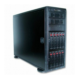
Chapter 1: Unpacking and Check Lists Chapter 1- Unpacking and Check Lists 1-A. The SC942S-600 chassis The SC942S chassis contains the following: One (1) 5.25" drive bay (for floppy drive) Two (2) 5.25" drive bays (for peripheral drives) Ten (10) SCA 1" drive trays Three (3) Hot-swappable 120mm chassis fans One (1) 120mm rear exhaust fan The accessory box contains the following:... - Page 4 SUPER SC942 Chassis User's Guide 1-B. The SC942i chassis The SC942i chassis contains the following: Eight (8) 5.25" peripheral drive bays One (1) 5.25" drive bay for floppy drive Three (3) Hot-swappable120mm chassis fans (*SC 942i-600) Two (2) Hot-swappable120mm chassis fans (*SC 942i-550) One (1) 120mm Rear Exhaust fan Two (2) Front accessible USB 2.0 ports The accessory box contains the following:...
-
Page 5: Chapter 2: Installation Procedures
Chapter 2: Installation Procedures Chapter 2: Installation Procedures Section 1: Installing Components into the SC942 Chassis A. Removing the Side Cover of the SC942 Chassis Before installing any components, replacing chassis fans or accessing the motherboard, you will first need to remove the side cover. Procedures 1. -
Page 6: Removing The Scsi Drive Trays
SUPER SC942 Chassis User's Guide B. Removing the SCSI Drive Trays (*SC942S) Procedures 1.Pull out the SCSI Drive Trays located on the front side of the chassis(*SC942S only) P u l l t h e S C S I D r i v e Trays outwards 2. -
Page 7: Removing The Rear Exhaust Fan And Installing The Motherboard
Chapter 2: Installation Procedures C. Removing the Rear Exhaust Fan and Installing the Motherboard (You will need to remove the rear exhaust fan before you install the motherboard.) Procedures 1. Remove the side cover from the chassis (refer to Section A). 2. -
Page 8: Removing The Components From And Installing Devices Into The 5.25" Drive Bays
SUPER SC942 Chassis User's Guide D. Removing Components from and Installing Devices into the 5.25" Drive Bays After removing the side cover from the chassis, you can remove or install devices into the drive bays (See Section A for removing the side cover). Procedures 1. -
Page 9: Installing The Rear Chassis Lock
Chapter 2: Installation Procedures E. Installing the Rear Chassis Lock Follow the procedures listed below to install the Rear Chassis Lock. Procedures 1. Locate the hole at the right bottom corner of the rear side of the chassis. Also locate the lock bracket included in your shipping package. lock bracket Hole for the lock bracket 2. - Page 10 SUPER SC942 Chassis User's Guide 3. Slide the side cover back to the proper position. Make sure that the lock bracket is easily accessible from the rear of the chassis. Lock Bracket 4. Secure the system by putting a lock(*not included) on the lock bracket as shown below: Lock (*Not included)
-
Page 11: Removing The Front Side Cover To Access The Drives
Chapter 2: Installation Procedures F. Removing the Front Side Cover to Access the Drives (You do not need to remove the front bezel to access the drives. We do not recommend removing the front cover unless you need to access the control panel circuit board or the floppy drive.) Procedures 1. - Page 12 SUPER SC942 Chassis User's Guide 4. Push on the open side of cover to completely remove it from the chassis. (*Do not swing or pull the front cover straight out after opening the left side.) 5. You can also remove the control panel's circuit board by removing the screw that fastens the control panel to the chassis.
-
Page 13: Section 2: Installing The Sc942 As A Rackmount
Chapter 2: Installation Procedures Section 2: Installing the SC942 as a Rackmount G. Rackmount Rail Kit: CSE-PT26 (* CSE-PT26 Sold separately.) CSE-PT26 Rackmount kit (*For beige chassis), or CSE-PT26 (B) Rackmount kit(*For black chassis) Two (2) handle sets for rackmount chassis Two (2) rack rail assemblies Two (2) front brackets for mounting rack rails Two (2) rear brackets for mounting rack rails... - Page 14 SUPER SC942 Chassis User's Guide H. Removing the Top Chassis Cover and Chassis Feet to Install as Rackmount Procedures 1. Remove the side cover from the chassis (See Section A). 2. Press the release tab in the center of the cover lip while pushing the cover toward the rear of the chassis at the same time.
-
Page 15: Attaching Chassis Ears To The Chassis
Chapter 2: Installation Procedures I. Attaching Chassis Ears to the Chassis After you have removed chassis feet from the chassis, you can now attach chassis ears to the chassis. Procedures 1. Remove the chassis feet from the chassis (See Section H). 2. -
Page 16: Installing Chassis Rails
SUPER SC942 Chassis User's Guide J. Installing Chassis Rails After you have attached the chassis ears to the chassis, you can install chassis rails to the chassis for rackmount purpose. Procedures 1. Included in the shipping package are a pair of rail assemblies. In each rail assembly, locate the inner rail and the outer rail. -
Page 17: Rack Installation
Chapter 2: Installation Procedures K. Rack Installation After you have installed the inner rails and chassis ears to the chassis, you are ready to install the outer rails of rail assemblies to the rack. Procedures 1. In the package, locate a pair of short brackets, and a pair of long brack- ets. - Page 18 SUPER SC942 Chassis User's Guide 5. Align brackets flush against the racks and tighten two screws through the holes of the rack (as shown below) and repeat the same step to install the rack on the other side. Use two M5 screws and washers attach bracket to the rack.
- Page 19 Chapter 2: Installation Procedures 7. To mount the SC942 on the rack, first you need to align both of the inner slides that are attached on the SC942 against the outer rails as shown below: Outer rails Inner rails 8. Slide the SC942 Assemblies all the way to the back of the slide rails to ensure that the assemblies are securely latched on the ball bearing slides.
- Page 20 SUPER SC942 Chassis User's Guide 9. Secure the SC942 by tightening the screws on the sides of the SC942 as shown above. s c r e w s 2-16...
-
Page 21: Appendix A: Cse-M35S/Cse-M35T1 Mobile Rack
Appendix A CSE-M35S/CSE-M35T1 Mobile Rack User's Guide Rev. 1.0... - Page 22 UPER SC942 Chassis User's Guide CSE-M35S/CSE-M35T1 Supermicro’s CSE-M35S/CSE-M35T1 Mobile Rack Series offers the cutting edge technology with greater flexibility. The CSE-M35T1 supports five Se- rial ATA hot-swappable hard drives that yield a unparalleled storage capac- ity without compromising productivity by eliminating possible system downtime.The CSE-M35S also accommodates five SCSI SCA 320/160 Hard...
-
Page 23: Technical Specifications
Appendix A: S UPER CSE-M35S/CSE-M35T1 User's Guide B. Technical Specifications Occupancy Three (3) 5.25" Drive Bays Capacity Five (5) 1" SCA Ultra320/160 Hard Drives with SAF-TE built-in (*CSE-M35S only) Five (5) 1" Host Receptacle Connectors, SATA hot-swap hard drives (*CSE-M35T-1 only) Cooling One (1) 9cm Exhaust Fan Subsystem... - Page 24 UPER SC942 Chassis User's Guide C. Jumper Settings C-1. Jumper Settings for the CSE-M35S (SCSI): Jumper Description Setting JP18 Buzzer Reset Closed: Enable, Open: Disable (*Default) JP21 SCSI Termination Closed: Enable (*Default), Open: Disable JP24 SCSI ID Selection 1-2: SCSI Ids: 0,1,2,3,4 (*Default), 2-3: SCSI Ids: 9,10,11,12,13 JP29 GEM 318 IDs...
- Page 25 Appendix A: S UPER CSE-M35S/CSE-M35T1 User's Guide C-2. Jumper Settings for the CSE-M35T1 (SATA): Jumper Description Setting JP18 Buzzer Reset Closed: Enable, Open: Disable (*Default) JP25 Overheat Temperature Open: 45 1-2: 50 C (*Default), 2-3: 55 JP26 Act#1-Act#5 Connect this header to CBL-0057 (SATA LED Cable) JP28: Fan Sense...
- Page 26 UPER SC942 Chassis User's Guide D. Installation Procedures D-1. Accessing Hot Swappable Drives: 1.Push the release button located beside the drive LEDs (as shown below:) 2. Swing the handle outward and pull out the unit (as shown below:) 3. Mount a drive in a carrier (as shown below:)
- Page 27 Appendix A: S UPER CSE-M35S/CSE-M35T1 User's Guide D-2. Accessing the Exhaust Fan: 1.Push the tabs located on both sides of the unit (as shown be- low:) 2. Pull out the fan (as shown below:) (*Note: For the SC-942 Chassis, the CSE-M35 Rear Exhaust Fan should not be used.
- Page 28 UPER SC942 Chassis User's Guide D-3. Accessing the Drive Backplane: 1. Unscrew the screw located on the side of the unit (as shown below:) 2. Pull out the Rear Bracket (as shown below:) 3. Access the Backplane (as shown below:)
-
Page 29: Appendix B: Power Supply Specifications
UPER SC942 Chassis User's Guide Appendix B Power Supply Specifications Please refer to the following table for Power Supply Specifications: Power Supply Spec SC942S-600 SC942i-600 SC942i-550 Model # SP602-TS SP602-TS SP550-RP Part # PWS-044 PWS-044 PWS-046 Rated AC Input Voltage 100-240V AC... - Page 30 Appendix B: Power Supply Specifications Notes...
-
Page 31: Appendix C: Scsi (Super) Gem Driver Installation Instructions For Windows Os
6) Click “Next” 2 times, uncheck both “Floppy disk drives” and “CD- ROM drives”. Then, select the item- “Specify a location,” and choose “Next”. 7) Click on “Browse” and choose D drive or wherever Supermicro Setup CD is in. 8) Choose “Qlogic” folder and click on “Open”. - Page 32 Appendix C: Installation Instuctions for the SCSI GEM Driver 5) At the first prompt, choose “Display a list of known device drivers for the device so that I can choose a specific driver” and click "Next". 6) Choose “Other Devices” and click Next. 7) Choose “Have Disk”, and specify your floppy drive location in the options box.
Need help?
Do you have a question about the SC942i-550 and is the answer not in the manual?
Questions and answers