Table of Contents
Advertisement
Quick Links
Advertisement
Table of Contents

Related Manuals for Supermicro SC747 Series


Summary of Contents for Supermicro SC747 Series
- Page 1 SC747 Series Chassis USER’S MANUAL Revision 1.0d...
- Page 2 State of California, USA. The State of California, County of Santa Clara shall be the exclusive venue for the resolution of any such disputes. Supermicro's total liability for all claims will not exceed the price paid for the hardware product.
- Page 3 5.25" storage modules can rotate 90° to accommodate tower or rack-mounting configurations. This document lists compatible parts available when this document was published. Refer to the Supermicro web site for updates on supported parts and configurations.
-
Page 4: Table Of Contents
Supermicro SC747 Chassis Series User's Manual Contents Contacting Supermicro ......................7 Chapter 1 Introduction 1.1 Overview ..........................8 1.2 Shipping List .........................8 1.3 Chassis Features .........................9 CPU .............................9 Hard Drives .........................9 I/O Expansion Slots ......................9 Peripheral Drives .........................9 Other Features ........................9 1.4 Components .........................9 Chassis ..........................9... - Page 5 4.4 Configuring the Storage Module ..................32 Tower or Rack Configuration .....................32 Installing Drives in the Storage Module ................34 Adding Five Hard Drives Using a Supermicro Mobile Rack ..........39 4.5 Installing Hard Drives ......................41 Installing Hard Drives into the Chassis ................41 4.6 Installing the Motherboard ....................43...
- Page 6 Supermicro SC747 Chassis Series User's Manual Installing the Motherboard....................45 Installing an Active Heatsink .....................46 Internal Power and Data Connections ................47 Configuring the Expansion Slots ..................48 Installing Double-Width Graphics Cards ................50 4.7 System Fans ........................52 Replacing Mid-Chassis System Fans ................52 Replacing Rear Exhaust Fans ..................53 Adding Optional External Rear Fans (BTQ Model Only) ..........54...
-
Page 7: Contacting Supermicro
Super Micro Computer, Inc. 980 Rock Ave. San Jose, CA 95131 U.S.A. Tel: +1 (408) 503-8000 Fax: +1 (408) 503-8008 Email: marketing@supermicro.com (General Information) support@supermicro.com (Technical Support) Website: www.supermicro.com Europe Address: Super Micro Computer B.V. Het Sterrenbeeld 28, 5215 ML... -
Page 8: Chapter 1 Introduction
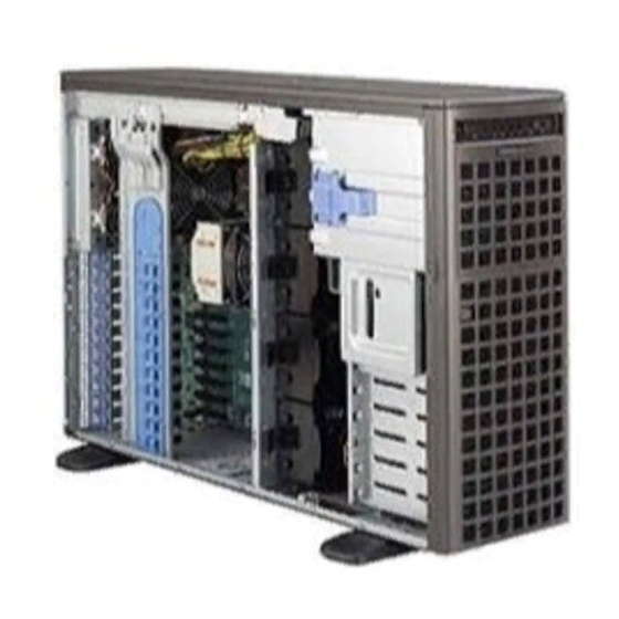
Chapter 1 Introduction 1.1 Overview Supermicro’s SC747 4U chassis features a unique and highly-optimized design. The chassis is equipped with high-efficiency power supplies. High-performance fans provide ample optimized cooling for the system and eight hot-swappable drive bays offer maximum storage capacity in a 4U form factor. -
Page 9: Chassis Features
LED indicators. 1.4 Components Chassis For the latest shipping lists, visit our website at: https://www.supermicro.com. This chassis accepts four hot-swappable system cooling fans and two power supplies. SC747 models come in dark gray. -
Page 10: Fans
1.5 Where to get Replacement Components If you need replacement parts for your system, to ensure the highest level of professional service and technical support, purchase exclusively from our Supermicro Authorized Distributors/System Integrators/Resellers. A list can be found at: https://www.supermicro.com. - Page 11 (http://www.supermicro.com/ support/rma/). Whenever possible, repack the chassis in the original Supermicro carton, using the original packaging material. If these are no longer available, be sure to pack the chassis securely, using packaging material to surround the chassis so that it does not shift within the carton and become damaged during shipping.
-
Page 12: Chapter 2 System Interface
Supermicro SC747 Chassis User's Manual Chapter 2 System Interface 2.1 Overview There are several LEDs on the control panel as well as others on the drive carriers to keep you constantly informed of the overall status of the system as well as the activity and health of specific components. -
Page 13: Control Panel Buttons
Chapter 2: System Interface 2.2 Control Panel Buttons There are two push-buttons located on the front of the chassis, a power on/off button and a reset button. • Power: The main power switch is used to apply or remove power from the power supply to the server system. -
Page 14: I/O Ports
Supermicro SC747 Chassis User's Manual • Overheat/Fan Fail: When this LED flashes it indicates a fan failure. When continuously on (not flashing) it indicates an overheat condition, which may be caused by cables obstruct- ing the airflow in the system or the ambient room temperature being too warm. Check the routing of the cables and make sure all fans are present and operating normally. -
Page 15: Drive Carrier Leds
Chapter 2: System Interface 2.5 Drive Carrier LEDs Your chassis uses SAS/SATA drives. SAS/SATA Drives Each SAS/SATA drive carrier has two LEDs. • Green: Each Serial ATA drive carrier has a green LED. When illuminated, this green LED (on the front of the SATA drive carrier) indicates drive activity. A connection to the SATA backplane enables this LED to blink on and off when that particular drive is being accessed. -
Page 16: Where To Get Replacement Components
(http://www.supermicro.com/ support/rma/). Whenever possible, repack the chassis in the original Supermicro carton, using the original packaging material. If these are no longer available, be sure to pack the chassis securely, using packaging material to surround the chassis so that it does not shift within the carton and become damaged during shipping. -
Page 17: Chapter 3 Rack Installation
Chapter 3: Rack Installation Chapter 3 Rack Installation 3.1 Overview This chapter provides instructions for installing your system into a rack environment. Following the instructions in the order given should enable you to install the system within a minimal amount of time. 3.2 Unpacking the System You should inspect the box the chassis was shipped in and note if it was damaged in any way. -
Page 18: Rack Precautions
Supermicro SC747 Chassis User's Manual Rack Precautions • Ensure that the leveling jacks on the bottom of the rack are fully extended to the floor with the full weight of the rack resting on them. • In single rack installation, stabilizers should be attached to the rack. -
Page 19: Mechanical Loading
Chapter 3: Rack Installation Mechanical Loading Equipment should be mounted into a rack so that a hazardous condition does not arise due to uneven mechanical loading. Circuit Overloading Consideration should be given to the connection of the equipment to the power supply circuitry and the effect that any possible overloading of circuits might have on overcurrent protection and power supply wiring. -
Page 20: Installing The Chassis Into A Rack
Supermicro SC747 Chassis User's Manual 3.4 Installing the Chassis into a Rack This section provides information on installing the SC747 chassis into a rack unit with the rails provided. There are a variety of rack units on the market, which may mean the assembly procedure will differ slightly. - Page 21 Chapter 3: Rack Installation Removing the Chassis Top Cover 1. Locate the chassis cover lock (blue lever) at the rear of the chassis cover. 2. Slide the chassis cover lock to the right and push chassis cover forward. 3. Lift the chassis top cover off the chassis. Removing the Chassis Feet 1.
-
Page 22: Identifying The Sections Of The Rack Rails
Supermicro SC747 Chassis User's Manual Identifying the Sections of the Rack Rails The chassis package includes two rack rail assemblies in the rack mounting kit. Each assembly consists of two sections: An inner fixed chassis rail that secures directly to the server chassis and an outer fixed rack rail that secures directly to the rack itself. -
Page 23: Installing The Chassis Handles And Inner Rails
Chapter 3: Rack Installation Figure 3-3. Installing the Inner Rack Rails Installing the Chassis Handles and Inner Rails Installing the Inner Rails 1. Locate the chassis handles and handle screws. 2. Align the chassis handle with the front of the chassis and secure with the three chassis handle screws. -
Page 24: Installing The Outer Rails To The Rack
Supermicro SC747 Chassis User's Manual Rear Rail Middle Rail Secure to the Rear of the Rack Attach to Middle Rail Slide into the Inner Rail Figure 3-4. Assembling the Outer Rails Installing the Outer Rails to the Rack Installing the Outer Rails 1. -
Page 25: Installing The Chassis Into A Rack
Chapter 3: Rack Installation Figure 3-5. Installing the Rack Rails Note: figures are for illustrative purposes only. Always install servers into racks from the bottom up. Installing the Chassis into a Rack Installing the Chassis 1. Confirm that chassis includes the inner rails and the outer rails. 2. -
Page 26: Tower Mounting Instructions
Supermicro SC747 Chassis User's Manual 3.5 Tower Mounting Instructions The SC747 chassis is shipped with the chassis cover and feet pre-installed. To use the chassis as a desktop server, no other installation is required. Use the instructions in this section if you have converted the chassis for rack use and need to return the chassis to tower mounting. -
Page 27: Installing Feet On The Chassis
Chapter 3: Rack Installation Chassis Foot Receptacle Chassis Foot Chassis Screws Figure 3-7. Placing Chassis Feet Installing Feet on the Chassis Installing the Chassis Feet 1. Place the chassis foot in the foot receptacle and slide the foot toward the front of the chassis. -
Page 28: Chapter 4 Chassis Setup And Maintenance
Supermicro SC747 Chassis User's Manual Chapter 4 Chassis Setup and Maintenance 4.1 Overview This chapter covers the steps required to install components and perform maintenance on the chassis. The only tool you will need to install components and perform maintenance is a Phillips screwdriver. -
Page 29: Chassis Covers
Chapter 4: Chassis Setup and Maintenance 4.3 Chassis Covers The SC747 chassis has three covers: the main cover, the top cover and the front cover. This section of the manual is describes removing the main cover, and opening the front cover. Removing the top cover is described in Chapter 6, in the section titled Installing a Chassis onto a Rack. -
Page 30: Removing The Main Cover
Supermicro SC747 Chassis User's Manual Removing the Main Cover Removing the Chassis Main Cover 1. Power down the system and remove the power cords from the rear of the power supplies. 2. Lift up and back on the main cover handle, which secures the cover to the chassis. -
Page 31: Opening The Front Cover
Chapter 4: Chassis Setup and Maintenance Opening the Front Cover The front cover houses up to eight hot-swappable hard drives. The cover can be locked to prevent unauthorized access. The key to this lock is shipped with the system. Opening the Front Cover 1. -
Page 32: Configuring The Storage Module
Supermicro SC747 Chassis User's Manual 4.4 Configuring the Storage Module Tower or Rack Configuration The SC747 chassis is shipped in tower mode and can be immediately used as desktop server. If the chassis is to be used in a rack, the storage module must be rotated 90 degrees and the storage moudule cover must be replaced with a horizontal module cover, part number MCP-210-74703-0B. - Page 33 Chapter 4: Chassis Setup and Maintenance Rotating the Storage Module for Rack Mounting 1. Power down the system, remove the power cords from the rear of the power supplies and open the chassis cover. 2. Locate the storage module and disconnect any cables from the storage module to any component in the chassis.
-
Page 34: Installing Drives In The Storage Module
More information on mobile rack installation can be found in the appendices at the end of this manual. Figure 4-7. Chassis Storage Module Warning! Enterprise level hard disk drives are recommended for use in Supermicro chassis and servers. For information on recommended HDDs, visit the Supermicro website at https://... - Page 35 Chapter 4: Chassis Setup and Maintenance Use the following instructions to add up to three peripheral drives (DVD-ROM, CD-ROM, etc.) to the drive trays: Adding Peripheral Drives 1. Power down the system, remove the power cords from the back of the power supplies and open the chassis cover.
- Page 36 Supermicro SC747 Chassis User's Manual 4. Remove the drive carrier rails from the drive carrier. To do this, you must remove two screws from each side. 5. Attach the rails to a DVD-ROM, DVD-RW or other peripheral. The rails should fit any standard sized 5.25"...
- Page 37 Chapter 4: Chassis Setup and Maintenance Adding Hard Drives to the Drive Carriers 1. Power down the server, unplug the power cords from the rear of the power supplies and open the chassis cover. 2. Locate the drive carrier release tab for the slot where you want to place the hard drive. 3.
- Page 38 Supermicro SC747 Chassis User's Manual 4. Place the hard drive into the drive carrier. Make sure The hard drive can be SAS or SATA depending on your motherboard. 5. Secure the hard drive to the carrier with four screws from the bottom.
-
Page 39: Adding Five Hard Drives Using A Supermicro Mobile Rack
The SC747 chassis supports a CSE-M35T-1/CSE-M35TQ mobile rack to install extra hot- swappable hard drives. The mobile rack goes into the storage module which goes into the chassis. For more information on mobile rack installation and use, visit the Supermicro website at https://www.supermicro.com. Adding Hard Drives to a Supermicro Mobile Rack 1. - Page 40 Supermicro SC747 Chassis User's Manual Hard Drive Rails Hard Drive Carrier Figure 4-13. Removing the Hard Drive Rails 3. Pull the first drive release tab and push the drive carrier toward the front of the chassis. Repeat this for all three tabs.
-
Page 41: Installing Hard Drives
The drives are mounted in drive carriers to simplify their installation and removal from the chassis. These carriers also help promote proper airflow for the drive bays. Only enterprise level hard drives are recommended for use in Supermicro chassis. Installing Hard Drives 1. - Page 42 Supermicro SC747 Chassis User's Manual 4. Remove the screws holding the dummy drive to the drive carrier. 5. Place a hard drive in the drive carrier. 6. Secure the hard drive to the carrier using four screws. Figure 4-16. Installing a Hard Drive 7.
-
Page 43: Installing The Motherboard
Chapter 4: Chassis Setup and Maintenance 4.6 Installing the Motherboard I/O Slot Shield Installation The I/O shield holds the motherboard ports in place. Install the I/O shield before installing the motherboard. I/O Shield Figure 4-17, SC747 Chassis I/O Shield Installing the I/O Shield 1. -
Page 44: Permanent And Optional Standoffs
Supermicro SC747 Chassis User's Manual Permanent and Optional Standoffs Standoffs prevent short circuits by creating space between the motherboard and the chassis surface. The SC747 chassis packaging includes optional standoffs (hexagon shaped posts). These standoffs accept the rounded Phillips head screws included in the SC747 accessories packaging. -
Page 45: Installing The Motherboard
Chapter 4: Chassis Setup and Maintenance Installing the Motherboard Installing the Motherboard into the Chassis 1. Review the documentation that came with your motherboard. Become familiar with component placement, requirements, and precautions. 2. Power down the system, disconnect the power cords from the power supplies, lay the chassis on a flat surface and open the chassis cover. -
Page 46: Installing An Active Heatsink
Supermicro SC747 Chassis User's Manual Installing an Active Heatsink Installation of the active heatsink will vary, depending upon the type of motherboard used in the chassis. See the information which was supplied with the motherboard for details on how to properly install the active heatsink on your specific motherboard. -
Page 47: Internal Power And Data Connections
Chapter 4: Chassis Setup and Maintenance Internal Power and Data Connections Connect each of the following cables, as required, by your motherboard manufacturer. In some instances, some cables may not need to be connected. Some cables may not be available with your model. -
Page 48: Configuring The Expansion Slots
Supermicro SC747 Chassis User's Manual Configuring the Expansion Slots After the motherboard installation, install expansion cards in the chassis. Installing Expansion Cards 1. Power down the system, unplug the power cords from the power supplies and open the chassis cover. - Page 49 Chapter 4: Chassis Setup and Maintenance 4. Pull the release tab upward. 5. Remove the screw holding the bracket in place and pull the bracket from the chassis. 6. Install your expansion card into the PCI slot bracket and motherboard. To do this, slide the expansion card (with "L"...
-
Page 50: Installing Double-Width Graphics Cards
The SC747 chassis is designed to support up to four double-width, high-end graphics cards. An eleven slot GPU card holder (MCP-290-74702-0N) is recommended for this application and may be purchased by visiting the Supermicro Web site at http://www.supermicro.com and clicking on the Where to Buy link. - Page 51 Chapter 4: Chassis Setup and Maintenance 3. Place the tabs of the MCP-290-74702-0N graphics card holder into the slots on the wall of the chassis as illustrated. 4. Lower the graphics card holder down onto the card 5. Pull back the slide lock and lower it over the raised tab as illustrated. 6.
-
Page 52: System Fans
Supermicro SC747 Chassis User's Manual 4.7 System Fans Six heavy-duty fans provide cooling for the chassis. Four system fans are located in the mid- section of the chassis with two exhaust fans in the rear. These fans circulate air through the system as a means of lowering the system's internal temperature. -
Page 53: Replacing Rear Exhaust Fans
Chapter 4: Chassis Setup and Maintenance Replacing Rear Exhaust Fans Replacing the Rear Exhaust Fan 1. Determine which fan is not operational. 2. Press the rear fan release tab. 3. Pull the fan away from the chassis by pulling back the top first. 4. -
Page 54: Adding Optional External Rear Fans (Btq Model Only)
Supermicro SC747 Chassis User's Manual Adding Optional External Rear Fans (BTQ Model Only) SC747BTQ chassis models support up to two optional external rear fans for additional cooling. These are mounted over the PCI slots in the rear of the chassis. These optional fans may be ordered separately (MCP-320-00046-0N-KIT). - Page 55 Chapter 4: Chassis Setup and Maintenance 4. Place two of the loose, metal bracket mounting pins into the holes at the base of the PCI slots in the position where the fan is to be located in the rear window. Tighten these pins to the rear window using pliers.
- Page 56 Supermicro SC747 Chassis User's Manual Phillips Head Mounting Screws Figure 4-29. Placing the External Rear Fan and Bracket on the Chassis 9. Push the top of the fan into the bracket until it clicks into the locked position. 10. Route the wiring through the open latch slot and into the chassis.
-
Page 57: Power Supply
Chapter 4: Chassis Setup and Maintenance 4.8 Power Supply The SC747 chassis is equipped with 2000W (redundant) power supplies. The power supply is auto-switching capable. This enables it to automatically sense and operate at a 100V to 240V input voltage. An amber light will be illuminated on the power supply when the power is off. -
Page 58: Chapter 5 Standardized Warning Statements For Ac Systems
Supermicro's Technical Support department for assistance. Only certified technicians should attempt to install or configure components. Read this appendix in its entirety before installing or configuring components in the Supermicro chassis. These warnings may also be found on our website at http://www.supermicro.com/about/... - Page 59 Chapter 5: Standardized Warning Statements Warnung WICHTIGE SICHERHEITSHINWEISE Dieses Warnsymbol bedeutet Gefahr. Sie befinden sich in einer Situation, die zu Verletzungen führen kann. Machen Sie sich vor der Arbeit mit Geräten mit den Gefahren elektrischer Schaltungen und den üblichen Verfahren zur Vorbeugung vor Unfällen vertraut. Suchen Sie mit der am Ende jeder Warnung angegebenen Anweisungsnummer nach der jeweiligen Übersetzung in den übersetzten Sicherheitshinweisen, die zusammen mit diesem Gerät ausgeliefert wurden.
- Page 60 Supermicro SC747 Chassis User's Manual . ٌ ا ك ً ف حالة و ٌ يك أى تتسبب ف اصابة جسذ ة ٌ هذا الزهز ع ٌ خطز !تحذ ز قبل أى تعول عىل أي هعذات،يك عىل علن بالوخاطز ال ا ٌجوة عي الذوائز...
- Page 61 Chapter 5: Standardized Warning Statements Warnung Vor dem Anschließen des Systems an die Stromquelle die Installationsanweisungen lesen. ¡Advertencia! Lea las instrucciones de instalación antes de conectar el sistema a la red de alimentación. Attention Avant de brancher le système sur la source d'alimentation, consulter les directives d'installation. .יש...
- Page 62 Supermicro SC747 Chassis User's Manual Warnung Dieses Produkt ist darauf angewiesen, dass im Gebäude ein Kurzschluss- bzw. Überstromschutz installiert ist. Stellen Sie sicher, dass der Nennwert der Schutzvorrichtung nicht mehr als: 250 V, 20 A beträgt. ¡Advertencia! Este equipo utiliza el sistema de protección contra cortocircuitos (o sobrecorrientes) del edificio.
- Page 63 Chapter 5: Standardized Warning Statements Power Disconnection Warning Warning! The system must be disconnected from all sources of power and the power cord removed from the power supply module(s) before accessing the chassis interior to install or remove system components. 電源切断の警告...
- Page 64 Supermicro SC747 Chassis User's Manual אזהרה מפני ניתוק חשמלי !אזהרה יש לנתק את המערכת מכל מקורות החשמל ויש להסיר את כבל החשמלי מהספק .לפני גישה לחלק הפנימי של המארז לצורך התקנת או הסרת רכיבים يجب فصم اننظاو من جميع مصادر انطاقت وإ ز انت سهك انكهرباء من وحدة امداد...
- Page 65 Chapter 5: Standardized Warning Statements Attention Il est vivement recommandé de confier l'installation, le remplacement et la maintenance de ces équipements à des personnels qualifiés et expérimentés. !אזהרה .צוות מוסמך בלבד רשאי להתקין, להחליף את הציוד או לתת שירות עבור הציוד واملدربيه...
- Page 66 Supermicro SC747 Chassis User's Manual Warnung Diese Einheit ist zur Installation in Bereichen mit beschränktem Zutritt vorgesehen. Der Zutritt zu derartigen Bereichen ist nur mit einem Spezialwerkzeug, Schloss und Schlüssel oder einer sonstigen Sicherheitsvorkehrung möglich. ¡Advertencia! Esta unidad ha sido diseñada para instalación en áreas de acceso restringido. Sólo puede obtenerse acceso a una de estas áreas mediante la utilización de una herramienta especial,...
- Page 67 Chapter 5: Standardized Warning Statements Battery Handling Warning! There is the danger of explosion if the battery is replaced incorrectly. Replace the battery only with the same or equivalent type recommended by the manufacturer. Dispose of used batteries according to the manufacturer's instructions 電池の取り扱い...
- Page 68 Supermicro SC747 Chassis User's Manual هناك خطر من انفجار يف حالة اسحبذال البطارية بطريقة غري صحيحة فعليل اسحبذال البطارية فقط بنفس النىع أو ما يعادلها مام أوصث به الرشمة املصنعة جخلص من البطاريات املسحعملة وفقا لحعليامت الرشمة الصانعة 경고! 배터리가 올바르게 교체되지 않으면 폭발의 위험이 있습니다. 기존 배터리와 동일하거나 제...
- Page 69 Chapter 5: Standardized Warning Statements ¡Advertencia! Puede que esta unidad tenga más de una conexión para fuentes de alimentación. Para cortar por completo el suministro de energía, deben desconectarse todas las conexiones. Attention Cette unité peut avoir plus d'une connexion d'alimentation. Pour supprimer toute tension et tout courant électrique de l'unité, toutes les connexions d'alimentation doivent être débranchées.
- Page 70 Supermicro SC747 Chassis User's Manual Backplane Voltage Warning! Hazardous voltage or energy is present on the backplane when the system is operating. Use caution when servicing. バックプレーンの電圧 システムの稼働中は危険な電圧または電力が、 バックプレーン上にかかっています。 修理する際には注意く ださい。 警告 当系统正在进行时,背板上有很危险的电压或能量,进行维修时务必小心。 警告 當系統正在進行時,背板上有危險的電壓或能量,進行維修時務必小心。 Warnung Wenn das System in Betrieb ist, treten auf der Rückwandplatine gefährliche Spannungen oder Energien auf.
- Page 71 Chapter 5: Standardized Warning Statements هناك خطز مه التيار الكهزبايئ أوالطاقة املىجىدة عىل اللىحة عندما يكىن النظام يعمل كه حذ ر ا عند خدمة هذا الجهاس 경고! 시스템이 동작 중일 때 후면판 (Backplane)에는 위험한 전압이나 에너지가 발생 합니다. 서비스 작업 시 주의하십시오. Waarschuwing Een gevaarlijke spanning of energie is aanwezig op de backplane wanneer het systeem in gebruik is.
- Page 72 Supermicro SC747 Chassis User's Manual תיאום חוקי החשמל הארצי !אזהרה .התקנת הציוד חייבת להיות תואמת לחוקי החשמל המקומיים והארציים تركيب املعدات الكهربائية يجب أن ميتثل للقىاويه املحلية والىطىية املتعلقة بالكهرباء 경고! 현 지역 및 국가의 전기 규정에 따라 장비를 설치해야 합니다.
- Page 73 Chapter 5: Standardized Warning Statements Attention La mise au rebut ou le recyclage de ce produit sont généralement soumis à des lois et/ou directives de respect de l'environnement. Renseignez-vous auprès de l'organisme compétent. סילוק המוצר !אזהרה .סילוק סופי של מוצר זה חייב להיות בהתאם להנחיות וחוקי המדינה التخلص...
- Page 74 Supermicro SC747 Chassis User's Manual Warnung Gefährlich Bewegende Teile. Von den bewegenden Lüfterblätter fern halten. Die Lüfter drehen sich u. U. noch, wenn die Lüfterbaugruppe aus dem Chassis genommen wird. Halten Sie Finger, Schraubendreher und andere Gegenstände von den Öffnungen des Lüftergehäuses entfernt.
- Page 75 Verbindungskabeln, Stromkabeln und/oder Adapater, die Ihre örtlichen Sicherheitsstandards einhalten. Der Gebrauch von anderen Kabeln und Adapter können Fehlfunktionen oder Feuer verursachen. Die Richtlinien untersagen das Nutzen von UL oder CAS zertifizierten Kabeln (mit UL/CSA gekennzeichnet), an Geräten oder Produkten die nicht mit Supermicro gekennzeichnet sind.
- Page 76 .قيرح وأ لطع يف ببستي دق ىرخأ تالوحمو تالباك يأ مادختسا .ميلسلا سباقلاو لصوملا مجح لبق نم ةدمتعملا تالباكلا مادختسا تادعملاو ةيئابرهكلا ةزهجألل ةمالسلا نوناق رظحيUL وأCSA ( ةمالع لمحت يتلاوUL/CSA) لبق نم ةددحملاو ةينعملا تاجتنملا ريغ ىرخأ تادعم يأ عمSupermicro.
- Page 77 사항을 준수하여 제공되거나 지정된 연결 혹은 구매 케이블, 전원 케이블 및 AC 어댑터를 사용하십시오. 다른 케이블이나 어댑터를 사용하면 오작동이나 화재가 발생할 수 있습니다. 전기 용품 안전법은 UL 또는 CSA 인증 케이블 (코드에 UL / CSA가 표시된 케이블)을 Supermicro 가 지정한 제품 이외의 전기 장치에 사용하는 것을 금지합니다. Stroomkabel en AC-Adapter...
- Page 78 Supermicro SC747 Chassis User's Manual Appendix A SC747 Chassis Cables A.1 Overview This appendix lists supported cables for your chassis system. It only includes the most commonly used components and configurations. For additional compatible cables, refer to the manufacturer of the motherboard you are using and our website at: A.2 Cables Included with SC747 Chassis (SAS/SATA)
- Page 79 Appendix A: Chassis Cabling A.3 Compatible Cables These cables are compatible with the SC747 chassis. Alternate SAS/SATA Cables Some compatible motherboards have different connectors. If your motherboard has only one SAS connector that the SAS/SATA cables must share, use one of the following cables. These cables must be purchased separately.
- Page 80 Supermicro SC747 Chassis User's Manual Extending Power Cables Although Supermicro chassis are designed with minimal cabling to be efficient and cost- effective, some compatible motherboards have power connectors located in different areas. To use these motherboards, you may have to extend the power cables to the motherboards.
-
Page 81: Appendix B Power Supply Specifications
Appendix B: Power Supply Specifications Appendix B Power Supply Specifications This appendix lists the power supply specifications for the SC747 chassis. Platinum Level 2000W (Redundant) MFR Part # PWS-2K04A-1R 1000W output @ 100-127V, 12-9.5 Amps, 50-60Hz 1800W output @ 200-240V, 10-9.5 Amps, 50-60Hz AC Input 1980W output @ 220-230V, 10-9.8 Amps, 50-60Hz 2000W output @ 230-240V, 10-9.8 Amps, 50-60Hz... -
Page 82: Appendix C Sas-747Tq Backplane Specifications
Supermicro SC747 Chassis User's Manual Appendix C SAS-747TQ Backplane Specifications To avoid personal injury and property damage, carefully follow all the safety steps listed below when accessing your system or handling the components. C.1 ESD Safety Guidelines Electrostatic Discharge (ESD) can damage electronic com ponents. To prevent damage to your system, it is important to handle it very carefully. - Page 83 The SAS-747TQ backplane has been designed to utilize the most up-to-date technology available, providing your system with reliable, high-quality performance. This manual reflects SAS-747TQ Revision 1.00, the most current release available at the time of publication. Always refer to the Supermicro website at www.supermicro.com for the...
- Page 84 Supermicro SC747 Chassis User's Manual C.5 Front Connectors UPGRADE JP69 JP18:BUZZER RESET JP18 JP68 JP35 JP25 SIDEBAND#2 SIDEBAND#1 JP35:9072 RST JP25:OH TEMP. JP97 1-2: RST OPEN:45 JP84:MODE JP98 2-3: NO RST 1-2:50 I2C#2 JP95 I2C#1 JP99 1-2:SGPIO 2-3:55 2-3:I2C SAS747TQ REV: 1.00...
- Page 85 Appendix C: SAS-747TQ Backplane Specifications C.6 Front Connector and Pin Definitions 1. Upgrade Connector T h e u p g r a d e c o n n e c t o r , designated JP69, is used for m a n u f a c t u r e r ' s d i a g n o s t i c purposes only.
- Page 86 Supermicro SC747 Chassis User's Manual 5. Backplane Main Power Backplane 4-pin Main Connectors Power Connector The 4-pin connectors designated Pin# Definition JP66 and JP68 provide power to +12V Ground the backplane. See the table on the right for pin definitions.
- Page 87 Appendix C: SAS-747TQ Backplane Specifications C.7 Front Jumper Locations and Pin Definitions JP69 JP18 JP84 JP98 UPGRADE JP69 JP18:BUZZER RESET JP18 JP35 JP99 JP35 JP25 JP68 SIDEBAND#2 SIDEBAND#1 JP35:9072 RST JP25:OH TEMP. JP97 JP97 1-2: RST OPEN:45 JP84:MODE JP98 2-3: NO RST 1-2:50 I2C#2 JP95...
- Page 88 Supermicro SC747 Chassis User's Manual Socket Settings Jumper Description Jumper Settings Buzzer reset* JP18 Connected to the front panel Press once to disable the buzzer Press twice to enable the buzzer *The buzzer sound indicates that a condition requiring immediate attention has occurred.
- Page 89 Appendix C: SAS-747TQ Backplane Specifications C and SGPIO Modes and Jumper Settings This backplane can utilize I2C or SGPIO. SGPIO is the default mode and can be used without making changes to your jumpers. The following information details which jumpers must be configured to use I2C mode or restore your backplane to SGPIO mode.
- Page 90 Supermicro SC747 Chassis User's Manual C.8 Front LED Indicators UPGRADE JP69 +5V LED FAN FAIL #1 #2 #3 LEDs +12V LED ALARM (Red, on) SIDEBAND#1 JP18:BUZZER RESET JP18 JP97 JP84:MODE JP98 I2C#1 JP99 1-2:SGPIO 2-3:I2C UPGRADE JP69 JP18:BUZZER RESET JP18...
- Page 91 Appendix C: SAS-747TQ Backplane Specifications C.9 Rear Connectors and LED Indicators FAIL#7 ACT#7 FAIL#0 ACT#0 FAIL#1 ACT#1 FAIL#2 ACT#2 FAIL#3 ACT#3 FAIL#4 ACT#4 FAIL#5 ACT#5 R149 FAIL#6 ACT#6 R165 R178 R173 R150 R164 Figure C-4. Rear Connectors Rear SAS/SATA Connectors Rear SAS Drive Connector...
-
Page 92: Appendix D M35T1 Mobile Rack Specifications
The CSE-M35T1 supports five Serial ATA hot-swappable hard drives that yield an unparalleled storage capacity without compromising productivity by eliminating possible system downtime. For support of the M35S mobile rack and all other SCSI support contact Supermicro's technical support department at www.supermicro.com. - Page 93 (https://www.supermicro. com/en/support/rma). Whenever possible, repack the mobile rack in the original Supermicro carton, using the original packaging material. If these are no longer available, be sure to pack the mobile rack securely, using packaging material to surround the mobile rack so that it does not shift within the carton and become damaged during shipping.
- Page 94 Supermicro SC747 Chassis User's Manual D.5 SATA-M35 Backplane Specifications To avoid personal injury and property damage, carefully follow all the safety steps listed below when accessing your system or handling the components. D.6 ESD Safety Guidelines Electrostatic Discharge (ESD) can damage electronic com ponents. To prevent damage to your system, it is important to handle it very carefully.
- Page 95 This manual reflects models SATA-M35 Revision 1.01, the most current release available at the time of publication. Always refer to the Supermicro website at http://www.supermicro.com for the latest updates, compatible parts and supported configurations.
- Page 96 Supermicro SC747 Chassis User's Manual D.9 SATA-M35 Front Connectors Figure D-11. SATA-M35 Front Connectors Front Connectors Front Connectors Number Description 4-pin Power Connectors: JP10 and JP13 ACT IN: JP26 Fan Connector: JP22 SATA Port #1 (Channel 1): J5 SATA Port #2 (Channel 2): J6...
- Page 97 Appendix D: M35T1 Mobile Rack Specifications D.10 Front Connectors and Pin Definitions 1. Backplane Main Power 4-pin Main Power Connectors Connector The 4-pin power connectors Pin# Definition provide power to the mobile rack. +12V Ground See the table on the right for pin definitions.
- Page 98 Supermicro SC747 Chassis User's Manual D.11 SATA-M35 Front Jumpers and Pin Definitions JP25 JP18 JP28 Figure D-2. SATA-M35 Front Jumpers SATA-M35 Front Jumper Settings Jumper Jumper Settings Note Open (jumper off): Buzzer enabled Buzzer reset* JP18 Closed (jumper on): Buzzer disabled...
- Page 99 Appendix D: M35T1 Mobile Rack Specifications D.12 Rear Connectors and LED Indicators The rear of the mobile rack backplane has SATA connectors and LEDs which display activity or failure status for each of the drives, as well as overheat and drive failure status. S-ATA #1 FAIL #1 ACT #1...
- Page 100 Supermicro SC747 Chassis User's Manual Rear SAS/SATA Connectors Rear SAS/SATA Reference Connector Drive Number S-ATA #1 SATA HDD #0 S-ATA #2 SATA HDD #1 S-ATA #3 SATA HDD #2 S-ATA #4 SATA HDD #3 S-ATA #5 SATA HDD #4 Rear LED Indicators...
- Page 101 5. Follow the installation procedures in the following section of this manual to remove and install the hard drives, cooling fan, and the back panel of the mobile rack. Warning! Enterprise level hard disk drives are recommended for use in Supermicro chassis and servers. For information on recommended HDDs, visit the Supermicro website at https:// www.supermicro.com/en/products/storage/superstorage/drives...
- Page 102 Supermicro SC747 Chassis User's Manual D.14 Installation Procedures Use the following installation procedures to set up the mobile rack. WARNING! SAS IDs are assigned automatically by the backplane. Do not set ID's manually on the drives. SAS termination is enabled by default on the SAS backplane.
- Page 103 Appendix D: M35T1 Mobile Rack Specifications Figure D-4. Removing Hard Drives From the Mobile Rack 2. Use the drive handle to carefully pull the drive from the mobile rack. Installing Hard Drives into the Hard Drive Carriers Dummy Drive Hard Drive Carrier Figure D-5.
- Page 104 Supermicro SC747 Chassis User's Manual Figure D-6. Removing the Dummy Drive from a Hard Drive Carrier Installing a Hard Drive into a Hard Drive Carrier 1. Remove the two screws holding securing the dummy drive to the hard drive carrier.
- Page 105 Appendix D: M35T1 Mobile Rack Specifications Connecting Cables to the Mobile Rack Before connecting cables the mobile rack, the exhaust fan must be removed. In some circumstances, the backplane may also need to be removed. Figure D-8. Removing Mobile Rack Fan Removing the Exhaust Fan and Connecting Cables 1.
- Page 106 Supermicro SC747 Chassis User's Manual Figure D-9. Removing Mobile Rack Fan 2. Pull the exhaust fan off the rear of the mobile rack. Figure D-10. Removing the Bracket Screw 3. Remove the bracket screw from the side of the mobile rack.
- Page 107 Appendix D: M35T1 Mobile Rack Specifications Figure D-11. Removing Mobile Rack Bracket 4. Pull the bracket from the rear of the mobile rack. 5. Connect the SATA cables and power cables to the backplane of the mobile rack. 6. Replace the bracket, the bracket screw, and the fan on the mobile rack and reconnect power to the chassis.
- Page 108 Supermicro SC747 Chassis User's Manual Additional Optional Installation Information If necessary, before reassembling the mobile rack, the backplane may be removed. To remove the mobile rack backplane, remove the six screws securing the backplane to the mobile rack. Carefully pull the backplane from the rear of the mobile rack.
-
Page 109: Appendix E M35Tq Mobile Rack Specifications
It provides the user with detailed information for the installation and use of the M35TQ mobile rack. The Supermicro M35TQ mobile rack supports SAS or SATA hard drives, and can accommodate up to five 3.5" hard drives or three 5.25" hard drives. The M35TQ showcases today's most... - Page 110 Supermicro SC747 Chassis User's Manual System Monitoring • Fan failure LED. • Overheat LED indicator. • Drive activity indicator. E.3 An Important Note to the User The pictures or graphics shown in this User's Guide were based upon the latest PCB revision available at the time of the publishing of this manual.
- Page 111 This manual reflects SAS-M35T Revision 1.01, the most current release available at the time of publication. Always refer to the Supermicro Web site at https://www.supermicro.com for the...
- Page 112 Supermicro SC747 Chassis User's Manual E.6 Front Connectors Figure E-1. Front Connectors Front Connectors Front Connectors Number Description 4-pin Power Connectors: JP10 and JP13 MG9072 Chip JTAG Connector: JP47 C Connector #1: JP44 C Connector #1: JP45 Sideband Connector #1: JP51...
- Page 113 Appendix E: M35TQ Mobile Rack Specifications E.7 Front Connectors and Pin Definitions 1. Mobile Rack Main Power Connectors Mobile Rack Main Power 4-Pin Connector The 4-pin power connectors, Pin# Definition designated JP10 and JP13, +12V provide power to the mobile rack. Ground See the table on the right for pin definitions.
- Page 114 Supermicro SC747 Chassis User's Manual 6. and 7. Sideband Headers Sideband Headers T h e s i d e b a n d h e a d e r s a r e Pin# Definition Pin# Definition designated JP51 and JP52.
- Page 115 Appendix E: M35TQ Mobile Rack Specifications E.8 Front Jumper Locations and Pin Definitions JP62 JP38 JP29 JP50 JP36 JP37 JP40 JP41 JP33 JP43 JP61 JP34 JP42 JP18 Figure E-2. Front Jumpers Explanation of Jumpers Connector To modify the operation of the mobile rack, jumpers can be Pins used to choose between optional settings.
- Page 116 Supermicro SC747 Chassis User's Manual JP29 JP18 Figure E-3. Buzzer and Chip Reset Jumpers Buzzer and Chip Reset Jumper Settings Buzzer/Chip Reset Jumper Settings Jumper Jumper Settings Note Open: Enabled Buzzer reset* JP18 Closed: Disabled Open: Default MG9072 chip reset...
- Page 117 Appendix E: M35TQ Mobile Rack Specifications JP62 JP61 Figure E-4: Fan Jumpers Fan Jumper Settings This mobile rack can utilize up to four fans. To use each fan, you must configure both jumpers as instructed below. Fan Jumper Settings Jumper Jumper Settings Note Closed: With fan...
- Page 118 Supermicro SC747 Chassis User's Manual JP38 JP50 JP37 JP36 JP40 JP41 JP33 JP43 JP34 JP42 Figure E-5. I C and SGPIO Jumpers C and SGPIO Modes and Jumper Settings This mobile rack can utilize I C or SGPIO. I C is the default mode and can be used without making changes to your jumpers.
- Page 119 Appendix E: M35TQ Mobile Rack Specifications E.9 Rear Connectors and LED Indicators The rear of the mobile rack backplane has SAS/SATA connectors and LEDs which display activity or failure status for each of the drives, as well as overheat and drive failure status. SAS #0 FAIL #0 ACT #0...
- Page 120 Supermicro SC747 Chassis User's Manual Rear SAS/SATA Connectors Rear SAS/SATA Connector Drive Number SAS #0 SAS/SATA HHD #0 SAS #1 SAS/SATA HHD #1 SAS #2 SAS/SATA HHD #2 SAS #3 SAS/SATA HHD #3 SAS #4 SAS/SATA HHD #4 Rear LED Indicators...
- Page 121 Appendix E: M35TQ Mobile Rack Specifications E.10 Preparing for Installation Tools Required The following tools are required to install the mobile rack into the chassis: • Phillips head screwdriver. • Antistatic strap (recommended). Important Safety Guidelines This product should be assembled and/or serviced by qualified and experienced technicians. To avoid personal injury and property damage, carefully follow the guidelines listed below.
- Page 122 Supermicro SC747 Chassis User's Manual E.11 Installation Procedures Use the following installation procedures to set up the mobile rack. WARNING! SAS IDs are assigned automatically by the backplane. Do not set ID's manually on the drives. SAS termination is enabled by default on the SAS backplane.
- Page 123 Appendix E: M35TQ Mobile Rack Specifications Dummy Drive Drive Carrier Figure E-8. Chassis Drive Carrier Warning: Except for short periods of time while swapping hard drives, do not operate the server with the mobile rack hard drive bays empty. The hard drive carriers must have a hard drive or a dummy drive installed.
- Page 124 Repeat these steps for each hard drive you want to install. Warning! Enterprise level hard disk drives are recommended for use in Supermicro chassis and servers. For information on recommended HDDs, visit the Supermicro website at https:// www.supermicro.com/en/products/storage/superstorage/drives...
- Page 125 Appendix E: M35TQ Mobile Rack Specifications Connecting Cables to the Mobile Rack Before connecting cables the mobile rack, the exhaust fan must be removed. In some circumstances, the backplane may need to be removed. Figure E-11. Removing Mobile Rack Fan Removing the Exhaust Fan and Connecting SAS/SATA Cables 1.
- Page 126 Supermicro SC747 Chassis User's Manual Figure E-12. Removing Mobile Rack Fan 3. Remove the bracket screw from the side of the mobile rack. 4. Pull the bracket from the rear of the mobile rack. 5. Connect the SAS/SATA cables and power cables to the backplane of the mobile rack.
- Page 127 Appendix E: M35TQ Mobile Rack Specifications Figure E-13. Removing Mobile Rack Fan 6. Replace the bracket, bracket screw, and fan on the mobile rack and reconnect power to the chassis.
- Page 128 Disclaimer (cont.) The products sold by Supermicro are not intended for and will not be used in life support systems, medical equipment, nuclear facilities or systems, aircraft, aircraft devices, aircraft/emergency communication devices or other critical systems whose failure to perform be reasonably expected to result in significant injury or loss of life or catastrophic property damage.
Need help?
Do you have a question about the SC747 Series and is the answer not in the manual?
Questions and answers