
Related Manuals for Supermicro SC745S2-800VB


Summary of Contents for Supermicro SC745S2-800VB
- Page 1 UPER SC745 CHASSIS Series SC745TQ-R800(B) SC745S2-R800(B) SC745TQ-800(B) SC745S2-800V(B) USER’S MANUAL...
- Page 2 Clara County in the State of California, USA. The State of California, County of Santa Clara shall be the exclusive venue for the resolution of any such disputes. Supermicro's total liability for all claims will not exceed the price paid for the hardware product.
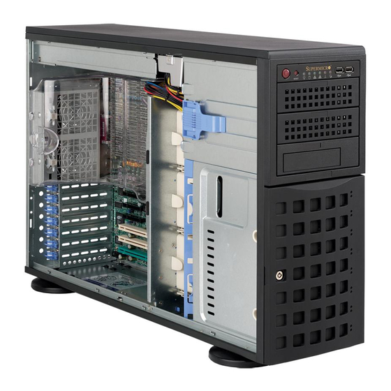
- Page 3 SC745 4U chassis. Installa- tion and maintenance should be performed by experienced technicians only. Supermicro’s SC745 4U chassis features a unique and highly-optimized design for dual-core Xeon platforms. The chassis is equipped with a 800W high effi ciency power supply for superb power savings.
- Page 4 SC745 Chassis Manual Notes...
-
Page 5: Preface
Preface Manual Organization Chapter 1: Introduction The fi rst chapter provides a checklist of the main components included with this chassis and describes the main features of the SC745 chassis. This chapter also includes contact information. Chapter 2: System Safety This chapter lists warnings, precautions, and system safety. - Page 6 SC745 Chassis Manual Compatible Backplanes This section lists compatible cables, power supply specifi cations, and compatible backplanes. Not all compatible backplanes are listed. Refer to our Web site for the latest compatible backplane information. Appendix A: Chassis Cables Appendix B: Power Supply Specifi cations Appendix C: SAS 743TQ Backplane Manual Appendix D: SCA 743S Backplane Manual...
-
Page 7: Table Of Contents
CPU ....................1-2 Hard Drives ................... 1-2 I/O Expansion slots ............... 1-2 Peripheral Drives ................1-2 Other Features ................1-2 Contacting SuperMicro ..............1-3 Chapter 2: System Safety Overview ....................1 Warnings and Precautions ..............1 Preparing for Setup ................1 Electrical Safety Precautions ............ - Page 8 To add up to three peripheral drives (DVD-ROM, CD-ROM, fl oppy drive, etc.) to the drive trays: ............5-9 To add fi ve hard drives using a SuperMicro mobile rack: ..5-11 Installation Step 2: Install Hard Drives ........5-13 To install hard drives to the chassis: ..........
- Page 9 Preface To install the air shroud ............... 5-21 To check the server's air fl ow ............. 5-22 Installation Complete ............... 5-22 System Fans .................. 5-23 To replace a system fan: ............. 5-23 To replace a rear chassis fan: ............ 5-24 Power Supply ................
- Page 10 SC745 Chassis Manual Appendices Appendix A: SC745 Chassis Cables Overview ..................A-1 Cables Included with SC745TQ Chassis (SAS/SATA) ....A-1 Cables Included with SC745S Chassis (SCSI) ......A-1 Compatible Cables ................. A-2 Alternate SAS/SATA Cables ..............A-2 Extending Power Cables ..............A-3 Front Panel to the Motherboard ............A-3 Appendix B: SC745 Power Supply Specifi...
-
Page 11: Chapter 1: Introduction
Chapter 1: Introduction Overview Supermicro’s SC745 4U chassis features a unique and highly-optimized design. The chassis is equipped with high effi ciency power supply. High performance fans provide ample optimized cooling for FB-DIMM memory modules and 8 hot-swap drive bays offer maximum storage capacity in a 4U form factor. -
Page 12: Chassis Features
SC745 Chassis Manual Chassis Features The SC745 4U high performance chassis includes the following features: The SC745 Chassis supports a DP Dual-core Xeon processor. Please refer to the motherboard specifi cations pages on our web site for updates on supported processors. -
Page 13: Contacting Supermicro
Chapter 1: Introduction Contacting SuperMicro Headquarters Address: SuperMicro Computer, Inc. 980 Rock Ave. San Jose, CA 95131 U.S.A. Tel: +1 (408) 503-8000 Fax: +1 (408) 503-8008 Email: marketing@supermicro.com (General Information) support@supermicro.com (Technical Support) Web Site: www.supermicro.com Europe Address: SuperMicro Computer B.V. - Page 14 SC745 Chassis Manual Notes...
-
Page 15: Chapter 2: System Safety
Chapter 2: System Safety Chapter 2: System Safety Overview This chapter provides a quick setup checklist to get your chassis up and running. Following the steps in order given should enable you to have your chassis setup and operational within a minimal amount of time. This quick set up assumes that you are an experienced technician, familiar with common concepts and terminology. -
Page 16: Electrical Safety Precautions
SC745 Chassis Manual Electrical Safety Precautions Basic electrical safety precautions should be followed to protect yourself from harm and the SC745 from damage: Be aware of the locations of the power on/off switch on the chassis as well as the room’s emergency power-off switch, disconnection switch or electri- cal outlet. -
Page 17: General Safety Precautions
Chapter 2: System Safety DVD-ROM Laser: CAUTION - this server may have come equipped with a DVD-ROM drive. To prevent direct exposure to the laser beam and hazard- ous radiation exposure, do not open the enclosure or use the unit in any unconventional way. - Page 18 SC745 Chassis Manual Touch a grounded metal object before removing any board from its anti- static bag. Do not let components or PCBs come into contact with your clothing, which may retain a charge even if you are wearing a wrist strap. Handle a board by its edges only;...
-
Page 19: Chapter 3: Chassis Components
Chassis Chassis include three 5.25" peripheral drive bays and eight hard drive bays. For the latest shipping lists, visit our Web site at: http://www.supermicro.com. This chassis accepts three hot-swappable system cooling fans and one (sometimes two) power supplies. SC745 models come in beige and black. -
Page 20: Power Supply
Supermicro Authorized Distributors / System Integrators / Resellers. A list of Supermicro Authorized Distributors / Sys- tem Integrators /Reseller can be found at: http://www.supermicro.com. Click the... -
Page 21: Chapter 4: System Interface
Chapter 4: System Interface Chapter 4: System Interface Overview There are several LEDs on the control panel as well as others on the drive carriers to keep you constantly informed of the overall status of the system as well as the activity and health of specifi... -
Page 22: Control Panel Buttons
Chassis Manual Control Panel Buttons There are two push-buttons located on the front of the chassis. These are power on/off button and a reset button. Power: The main power switch is used to apply or remove power from the power supply to the server system. Turning off system power with this but- ton removes the main power but keeps standby power supplied to the system. -
Page 23: Drive Carrier Leds
Chapter 4: System Interface NIC2: Indicates network activity on GLAN2 when fl ashing. NIC1: Indicates network activity on GLAN1 when fl ashing. HDD: Indicates IDE channel activity. SAS/SATA drive, SCSI drive, and/or DVD-ROM drive activity when fl ashing. Power: Indicates power is being supplied to the system's power supply units. -
Page 24: Scsi Drives
Chassis Manual connection to the SATA backplane enables this LED to blink on and off when that particular drive is being accessed. Red: The red LED to indicate an SAS/SATA drive failure. If one of the SAS/ SATA drives fail, you should be notifi ed by your system management software. SCSI Drives Each SCSI drive carrier has two LEDs. -
Page 25: Chapter 5: Chassis Setup And Maintenance
Chapter 5: Chassis Setup and Maintenance Chapter 5: Chassis Setup and Maintenance Overview This chapter covers the steps required to install components and perform maintenance on the chassis. The only tool you will need to install components and perform maintenance is a Phillips screwdriver. Print this page to use as a reference while setting up your chassis. -
Page 26: Installation Step 1: Remove The Chassis Cover
Chassis Manual Installation Step 1: Remove the Chassis Cover Front Cover Cover Latch Button Cover Latch Handle Figure 5-1: Removing the Chassis Cover To remove the chassis cover: 1. Push the cover latch button to release the latch handle. 2. Pull the cover off the chassis using the latch handle. To replace the chassis cover: 1. -
Page 27: The Front Cover
Chapter 5: Chassis Setup and Maintenance Front Cover Front Cover Lock Figure 5-2: Opening the Front Cover The Front Cover The front cover houses up to eight hot-swappable hard drives. The cover can be locked to prevent unauthorized access. The key to this lock is shipped with the system. -
Page 28: Installation Step 2: Confi Gure The Storage Module
Chassis Manual Installation Step 2: Confi gure the Storage Module Storage Module Figure 5-3: Chassis in Tower Mode Storage Module Figure 5-4: Chassis in Rack Mount Mode Tower or Rack Confi guration The SC745 chassis is shipped in tower mode and can be immediately used as desktop server. -
Page 29: To Rotate The Storage Module For Rack Mounting
Chapter 5: Chassis Setup and Maintenance Storage Module Storage Module Release Lever Figure 5-5: Remove the Storage Module To rotate the storage module for rack mounting: 1. Open the chassis cover. 2. Locate the storage module and disconnect any cables from the storage module to any component in the chassis. -
Page 30: Adding Drives To The Storage Module
Chassis Manual Figure 5-6: Chassis Storage Module Adding Drives to the Storage Module The storage module includes three full sized drive bays and the front LED panel. The storage module can be set up one of three ways: A. Add up to three extra hard drives to the drive trays. B. -
Page 31: To Add Up To Three Hard Drives To The Drive Trays
Chapter 5: Chassis Setup and Maintenance Drive Tray Release Tabs Figure 5-7: Remove Drive Tray To add up to three hard drives to the drive trays: 1. Open the chassis cover. 2. Locate the drive tray release tab for the slot you want to place the peripheral drive. - Page 32 Chassis Manual Hard Drive Tray Hard Drive Figure 5-8: Add a Hard Drive to the Drive Tray 4. Place the hard drive to the hard drive tray. Make sure The hard drive can be SAS or SCSI depending on your motherboard. The hard drive may not completely fi...
-
Page 33: To Add Up To Three Peripheral Drives (Dvd-Rom, Cd-Rom, Fl Oppy Drive, Etc.) To The Drive Trays
Chapter 5: Chassis Setup and Maintenance Drive Tray Release Tabs Figure 5-9: Remove Drive Tray To add up to three peripheral drives (DVD-ROM, CD-ROM, fl oppy drive, etc.) to the drive trays: 1. Open the chassis cover. 2. Locate the drive tray release tab for the slot you want to place the peripheral drive. - Page 34 Chassis Manual Hard Drive Tray Hard Drive Rails Figure 5-10: Add Hard Drive Rails to the DVD-ROM Drive 4. Remove the hard drive tray rails from the hard drive tray. To do this, you must remove two screws from each side. 5.
-
Page 35: To Add Fi Ve Hard Drives Using A Supermicro Mobile Rack
Release Tabs Figure 5-11: Remove Drive Tray To add fi ve hard drives using a SuperMicro mobile rack: The SC745 chassis accepts a CSE-M35S (SCSI) or CSE-M35T-1/CSE-M35TQ mobile rack to install extra hot swappable hard drives. The mobile rack goes into the storage module which goes into the chassis. - Page 36 Chassis Manual Hard Drive Rails Hard Drive Tray Figure 5-12: Remove the Hard Drive Rails 4. Remove the hard drive tray rails from the hard drive tray. To do this, you must remove two screws from each side. Do this for all three hard drive trays. 5.
-
Page 37: Installation Step 2: Install Hard Drives
Chapter 5: Chassis Setup and Maintenance Installation Step 3: Install Hard Drives Drive Tray Handle Release Button Figure 5-14: Install Hard Drives To install hard drives to the chassis: The drives are mounted in drive carriers to simplify their installation and removal from the chassis. - Page 38 Chassis Manual Drive Tray SAS/SATA or SCSI Hard Drive Figure 5-115: Remove Dummy Drive Tray 4. Remove the screws holding the drive tray to the dummy drive. 5. Place a hard drive in the drive tray. Figure 5-16: Install Hard Drive 6.
-
Page 39: Installation Step 3: Install The Motherboard
Chapter 5: Chassis Setup and Maintenance Installation Step 4: Install the Motherboard I/O Slot Shield The I/O shield holds the motherboard ports in place. Install the I/O shield before you install the motherboard. I/O Shield Figure 5-17: SC745 Chassis I/O Shield To install the I/O shield: 1. -
Page 40: Permanent And Optional Standoffs
Chassis Manual Permanent and Optional Standoffs Standoffs prevent short circuits by securing space between the motherboard and the chassis surface. The SC745 chassis packaging includes optional standoffs (hexagon shaped posts). These standoffs accept the rounded Phillips head screws included in the SC745 accessories packaging. Figure 5-18: Chassis Standoffs 5-16... -
Page 41: To Install The Motherboard
Chapter 5: Chassis Setup and Maintenance To install the motherboard: 1. Review the documentation that came with your motherboard. Become familiar with component placement, requirements, and precautions. 2. Disconnect the power supply and lay the chassis on a fl at surface. 3. -
Page 42: Power Supply Connections
HDD (Hard Drive) [FDD]). Attach the HDD connectors backplane power cable to the backplane. If you are using a SuperMicro backplane, the FDD con- nector does not need to be attached. Provides power to the motherboard CPU. 8-pin mother- mother-... -
Page 43: Add-On Card/Expansion Slot Setup
Chapter 5: Chassis Setup and Maintenance Lift the Press the Middle Release Tab of the Release Tab Figure 5-19: Add-on Card/Expansion Card Port Add-on Card/Expansion Slot Setup After motherboard installation, install add-on cards to the chassis, such as PCI cards. To install add-on and expansion cards: 1. - Page 44 Chassis Manual Figure 5-20: Remove PCI card slot guard 4. Remove the screw holding the bracket in place and pull the bracket from the chassis. 5. Install your PCI card or other add-on card into the PCI slot bracket and moth- erboard.
-
Page 45: Installation Step 4: Install The Air Shroud
Chapter 5: Chassis Setup and Maintenance Installation Step 5: Install the Air Shroud Removable Tabs Figure 5-21: Air Shroud Air shrouds concentrate airfl ow to maximize fan effi ciency. The SC745 chassis air shroud does not require screws to set up. NOTE: The air shroud includes tabs that can be removed if motherboard compo- nents prevent the air shroud from fi... -
Page 46: To Check The Server's Air Fl Ow
Chassis Manual Air Shroud Figure 5-22: Air Shroud in place To check the server's air fl ow 1. Make sure there are no objects to obstruct airfl ow in and out of the server. In addition, if you are using a front bezel, make sure the bezel's fi lter is replaced periodically. -
Page 47: System Fans
Chapter 5: Chassis Setup and Maintenance System Fans Five heavy duty fans provide cooling for the chassis. Three fans are located in the front of the chassis with two fans in the rear. These fans circulate air through the chassis as a means of lowering the chassis internal temperature. The fans come pre-installed to the chassis. -
Page 48: To Replace A Rear Chassis Fan
Chassis Manual Rear Fan Release Tab Figure 5-24: Rear Chassis Fans To replace a rear chassis fan: 1. Press the rear fan release tab. 2. Pull the fan from the chassis top fi rst. 3. Place the new fan in the chassis bottom fi rst. 4. -
Page 49: Power Supply
Chapter 5: Chassis Setup and Maintenance Power Supply Depending on your chassis model, the SC745 Chassis has a 700W or 800W (re- dundant) power supply. This power supply is auto-switching capable. This enables it to automatically sense and operate at a 100v to 240v input voltage. An amber light will be illuminated on the power supply when the power is off. - Page 50 Chassis Manual Notes 5-26...
-
Page 51: Chapter 6: Rack Installation
Chapter 6: Rack Installation Chapter 6: Rack Installation Overview This chapter provides a quick setup checklist to get your chassis up and running. Following these steps in the order given should enable you to have the system operational within a minimum amount of time. Unpacking the System You should inspect the box the chassis was shipped in and note if it was damaged in any way. -
Page 52: Rack Precautions
Chassis Manual Warnings and Precautions! Rack Precautions - Ensure that the leveling jacks on the bottom of the rack are fully extended to the fl oor with the full weight of the rack resting on them. - In single rack installation, stabilizers should be attached to the rack. - In multiple rack installations, the racks should be coupled together. -
Page 53: Reduced Airfl Ow
Chapter 6: Rack Installation Reduced Airfl ow Equipment should be mounted into a rack so that the amount of airfl ow required for safe operation is not compromised. Mechanical Loading Equipment should be mounted into a rack so that a hazardous condition does not arise due to uneven mechanical loading. -
Page 54: Rack Mounting Instructions
Chassis Manual Rack Mounting Instructions This section provides information on installing the SC745 chassis into a rack unit with the rails provided. There are a variety of rack units on the market, which may mean the assembly procedure will differ slightly. You should also refer to the installation instructions that came with the rack unit you are using. -
Page 55: To Remove The Chassis Top Cover
Chapter 6: Rack Installation To remove the chassis top cover 1. Locate the chassis cover lock (blue lever) at the rear of the chassis cover. 2. Slide the chassis cover lock to the right and push chassis cover forward. 3. Lift the chassis top cover off the chassis. To remove the chassis feet 1. -
Page 56: Identifying The Sections Of The Rack Rails
Chassis Manual Identifying the Sections of the Rack Rails The chassis package includes two rack rail assemblies in the rack mounting kit. Each assembly consists of two sections: an inner fi xed chassis rail that secures directly to the server chassis and an outer fi xed rack rail that secures directly to the rack itself. -
Page 57: To Install The Chassis Handles And Inner Rails
Chapter 6: Rack Installation Figure 6-3. Installing the Inner Rack Rails To install the chassis handles and inner rails 1. Locate the chassis handles (2) and handle screws (6). 2. Align the chassis handle with the front of the chassis and secure with the three chassis handle screws. -
Page 58: To Install The Outer Rails To The Rack
Chassis Manual Secure to the Rear of the Rack Attach to Middle Section Secure to the Front of the Rack Figure 6-4: Assembling the Outer Rails To install the outer rails to the rack 1. Attach the front and rear short brackets to the outside of the long bracket. Both bracket ends must face the same direction. -
Page 59: To Install The Chassis Into A Rack
Chapter 6: Rack Installation Figure 6-5. Installing the Rack Rails To install the chassis into a rack 1. Confi rm that chassis includes the inner rails and the outer rails. 2. Line chassis rails with the front of the rack rails (C). 3. -
Page 60: Tower Mounting Instructions
Chassis Manual Tower Mounting Instructions The SC745 chassis is shipped with the chassis cover and feet pre-installed. To use the chassis as a desktop server, no other installation is required. Use the instructions in this section if you have converted the chassis for rack use and need to return the chassis to tower mounting. -
Page 61: To Place Chassis Feet
Chapter 6: Rack Installation Chassis Foot Receptacle Chassis Foot Chassis Screw Figure 6-7: Placing Chassis Feet To place chassis feet 1. Place the chassis foot in the foot receptacle and slide the foot toward the front of the chassis. The foot should lock into place. 2. - Page 62 Chassis Manual Notes 6-12...
-
Page 63: Appendices
Appendicies Appendicies Appendix A: Compatible Cables Appendix B: SC745 Power Supply Specifi cations Appendix C: SCA 743S2 Backplane Manual Appendix D: SAS 743TQ Backplane Manual Appendix E: CSE-M35S/CSE-M35T1 Mobile Rack... - Page 64 Appendicies Notes...
-
Page 65: Appendix A: Sc745 Chassis Cables
This appendix lists supported cables for your chassis system. It only includes the most commonly used components and confi gurations. For more compatible cables, refer to the manufacturer of the motherboard you are using and our Web site at: www.supermicro.com. A-2 Cables Included with SC745TQ Chassis (SAS/SATA) SC745TQ-R800/800... -
Page 66: A-4 Compatible Cables
Chassis Manual A-4 Compatible Cables These cables are compatible with the SC745 Chassis. Alternate SAS/SATA Cables Some compatible motherboards have different connectors. If your motherboard has only one SAS connector that the SAS/SATA cables must share, use one of the following cables. -
Page 67: Extending Power Cables
Appendix A: Chassis Cables Extending Power Cables Although Super Micro chassis are designed with to be effi cient and cost-effective, some compatible motherboards have power connectors located in different areas. To use these motherboards you may have to extend the power cables to the mother boards. - Page 68 Chassis Manual Notes...
-
Page 69: Appendix B: Sc745 Power Supply Specifi Cations
Appendix B: Power Supply Specifi cations Appendix B: SC745 Power Supply Specifi cations This appendix lists power supply specifi cations for your chassis system. 800W (Redundant = X2) MFR Part # PWS-801-1R 100 - 240V Rated AC Voltage 50 - 60Hz 10 - 4 Amp +5V standby 4 Amp +12V 66 Amp... - Page 70 Chassis Manual Notes...
- Page 71 JP10 JP13 SCA 743S2 Backplane USER'S GUIDE Rev. 1.0...
- Page 72 Clara County in the State of California, USA. The State of California, County of Santa Clara shall be the exclusive venue for the resolution of any such disputes. Supermicro's total liability for all claims will not exceed the price paid for the hardware product.
- Page 73 Safety Information and Technical Specifi cations Table of Contents Chapter 1: Safety Guidelines ESD Safety Guidelines ..............1-1 General Safety Guidelines ............... 1-1 An Important Note to Users ............. 1-1 Chapter 2: Jumper Settings and Pin Defi nitions Front Connectors and Jumpers ............2-1 Front Connector and Pin Defi...
- Page 74 SCA 743S Backplane User's Guide Notes...
-
Page 75: Chapter 1: Safety Guidelines
Safety Information and Technical Specifi cations Chapter 1: Safety Guidelines To avoid personal injury and property damage, carefully follow all the safety steps listed below when accessing your system or handling the components. ESD Safety Guidelines Electric Static Discharge (ESD) can damage electronic com ponents. To prevent dam- age to your system, it is important to handle it very carefully. - Page 76 SCA 743S Backplane User's Guide Notes...
-
Page 77: Chapter 2: Jumper Settings And Pin Defi Nitions
Safety Information and Technical Specifi cations Chapter 2: Jumper Settings and Pin Defi nitions Front Connectors and Jumpers Buzzer JP10 JP13 Front Connectors 1. GEM 318 Chips 2. Backplane Main (4-Pin) PWR: JP10 and JP15 3. SCSI Channel A: LVD1 4. -
Page 78: Front Connector And Pin Defi Nitions
SCA 743S Backplane User's Guide Front Connector and Pin Defi nitions #1. GEM Chip (SAF-TE: SCSI Accessed SAF-TE LED Indicators Fault-Tolerant Enclosures) LED # Location Description The GEM chip allows the system to Front Overheat or Drive Failure (red light, fl ashing, buzzer monitor the status of the disk drives and provides disk drive information to the user Rear... - Page 79 Safety Information and Technical Specifi cations #3. and #4. Ultra 320 SCSI Connector Ultra320 SCSI Drive Connector Pin Defi nitions (LVD1 and LVD2) (LVD1 and LVD2) Pin# Defi nition Pin # Defi nition The Ultra 320 SCSI connectors, LVD1 +DB (12) -DB (12) and LVD2, join the backplane to the +DB (13)
-
Page 80: Front Jumper Locations And Pin Defi Nitions
SCA 743S Backplane User's Guide Front Jumper Locations and Pin Defi nitions JP18 JP14 JP23 JP20 JP10 JP13 JP22 Explanation of Jumpers Connector To modify the operation of the backplane, Pins jumpers can be used to choose between optional settings. Jumpers create shorts between two pins to change the function Jumper of the connector. - Page 81 Safety Information and Technical Specifi cations FRONT LED INDICATORS Backplane LED STATE SPECIFICATION Overheat/Drive Failure LED Indicator (Red light: fl ashing, Buzzer: On)
-
Page 82: Rear Connectors And Led Indicators
SCA 743S Backplane User's Guide Rear Connectors and LED Indicators SCA8 SCA2 SCA3 SCA4 SCA5 SCA6 SCA7 SCA1 Rear SCA Connectors Rear Connector SCA Drive Connector Number Number SCA1 A - ID #0 SCA HDD #0 SCA8 A - ID #1 SCA HDD #1 SCA2 A - ID #2... - Page 83 6. Click “Next” twice, uncheck both “Floppy disk drives” and “CD-ROM drives”. 7. Select “Specify a location,” and choose “Next”. 8. Click on “Browse” and choose D drive or wherever Supermicro Setup CD is in. 9. Choose “Qlogic” folder and click on “Open”.
- Page 84 SCA 743S Backplane User's Guide Notes...
- Page 85 M 8 5 M 8 7 M 8 6 M 9 7 M 9 5 M 8 4 M 9 6 M 9 4 UPER SAS743TQ M M 3 M M 2 REV 3.00 +12V +12V GND +5V M 8 2 M 8 1 M 8 0 M 8 9...
- Page 86 SAS 743TQ Backplane User’s Guide Table of Contents Safety Information and Technical Specifications ........1-3 1. Safety Guidelines ..................1-3 2. Jumper Settings and Pin Definitions ............1-4 A. Front Connectors and Jumpers ............... 1-4 A-1. Front Jumper/Connector Locations ..........1-4 A-2.
-
Page 87: Safety Information And Technical Specifications
Safety Information and Technical Specifications Safety Information and Technical Specifications 1. Safety Guidelines To avoid personal injury and property damage, please carefully follow all the safety steps listed below when accessing your system or handling the components: ESD Safety Guidelines Electric Static Discharge (ESD) can damage electronic components. -
Page 88: Jumper Settings And Pin Definitions
SAS 743TQ Backplane User’s Guide 2. Jumper Settings and Pin Definitions A. Front Connectors and Jumpers A-1 Front Jumper/Connector Locations Front View UPER SAS743TQ REV 3.00 +12V +12V GND +5V A-2. Front Connectors #1. JP10: 4-Pin PWR Connector #2. JP13: 4-Pin PWR Connector #3. -
Page 89: A-3. Front Connector Pin Definitions
Safety Information and Technical Specifications A-3. Front Connector Pin Definitions #1/#2. Backplane Main Power Connectors (JP10, JP13 ) Pin Definitions Backplane Main You must use the 4-pin power connectors: 4-pin Connector JP13, JP10 to provide adequate power to the (J10) Backplane. - Page 90 SAS 743TQ Backplane User’s Guide Front Jumper/LED Locations UPER SAS743TQ REV 3.00 +12V +12V GND +5V A-5 Front Jumpers and Pin Definitions Front Jumpers Jumper Note SGPIO C Setting Setting (*Default) JP18 Closed: Buzzer Reset Open Open JP29 Closed: MG9072 Reset Open Open JP33...
-
Page 91: A-6. Front/Rear Sas Connectors And Locations
Safety Information and Technical Specifications A-6 Front/Rear SAS Connectors and Locations Front View UPER SAS743TQ REV 3.00 +12V +12V GND +5V SAS#0 * Front/Rear SAS Connector Location Table Rear View... - Page 92 SAS 743TQ Backplane User’s Guide B. Rear Connectors and LED Indicators B-1 Rear SAS Connector/LED Indicator Locations Rear View...
-
Page 93: B-2. Rear Connector/Led Indicator Descriptions
Safety Information and Technical Specifications B-2 Rear Connector/LED Indicator Descriptions Rear SAS Connectors Rear SAS Connectors Connector Specification SAS#0 HDD (connected to HDD) SAS#1 HDD (connected to HDD) SAS#2 HDD (connected to HDD) SAS#3 HDD (connected to HDD) SAS#4 HDD (connected to HDD) SAS#5 HDD (connected to HDD) SAS#6 HDD (connected to HDD) SAS#7 HDD (connected to HDD) -
Page 94: B-3. The Ami Mg9072 Ses-2 Controller (Scsi Enclosure Services-2) Led Indicators
SAS 743TQ Backplane User’s Guide B-3 The AMI MG9072 SES-2 Controller (SCSI Enclosure Services-2) LED Indicators The AMI MG 9072 allows the system to use a set of pre-defined SES commands to monitor the status of disk drives and provide disk drive information to the user through LED indicators and alarms/buzzers. - Page 95 ® UPER CSE-M35S/CSE-M35T1 Mobile Rack USER'S GUIDE...
- Page 96 UPER CSE-M35S/CSE-M35T1 User's Guide Table of Contents Packaging List ...................... 3 Technical Specifications ..................4 Jumper Settings ....................5 Installation Procedures ..................7...
-
Page 97: Packing List
Packing List CSE-M35S/CSE-M35T1 Supermicro’s CSE-M35S/CSE-M35T1 Mobile Rack Series offers the cutting edge technology with greater flexibility. The CSE-M35T1 supports five Se- rial ATA hot-swappable hard drives that yield a unparalleled storage capac- ity without compromising productivity by eliminating possible system down- time. -
Page 98: Technical Specifications
UPER CSE-M35S/CSE-M35T1 User's Guide 2. Technical Specifications Occupancy Three (3) 5.25" Drive Bays Capacity Five (5) 1" SCA Ultra320/160 Hard Drives with SAF-TE built-in (*CSE-M35S only) Five (5) 1" Host Receptacle Connectors, SATA hot-swap hard drives (*CSE-M35T-1 only) Cooling One (1) 90mm (9cm) Exhaust Fan Subsystem System *Fan Fail Detection LED and Alarm... -
Page 99: Jumper Settings
Jumper Settings 3. Jumper Settings A. Jumper Settings for the CSE-M35S (SCSI): Jumper Description Setting JP18 Buzzer Reset Closed: Enable, Open: Disable (*Default) JP21 SCSI Termination Closed: Enable (*Default), Open: Disable JP24 SCSI ID Selection 1-2: SCSI Ids: 0,1,2,3,4 (*Default), 2-3: SCSI Ids: 9,10,11,12,13 JP29 GEM 318 IDs... - Page 100 UPER CSE-M35S/CSE-M35T1 User's Guide B. Jumper Settings for the CSE-M35T1 (SATA): Jumper Description Setting JP18 Buzzer Reset Closed: Enable, Open: Disable (*Default) JP25 Overheat Temperature Open: 45 1-2: 50 C (*Default), 2-3: 55 JP26 Act#1-Act#5 Connect this header to CBL-0057 (SATA LED Cable) JP28: Fan Sense...
-
Page 101: Installation Procedures
Installation Procedures 4. Installation Procedures (*Note: For the CSE-M35S: 1. SCSI IDs are assigned automatically by the backplane. Do not set IDs manually on the drives. See the previous section for SCSI ID jumper settings. 2. SCSI termination is enabled by default on the SCSI backplane.) A. - Page 102 UPER CSE-M35S/CSE-M35T1 User's Guide 2. Swing the handle outward and pull out the unit (as shown below:) 3. Mount a drive in a carrier (as shown below:)
- Page 103 Installation Procedures B. Accessing the Exhaust Fan: 1.Push the tabs located on both sides of the unit (as shown be- low:) 2. Pull out the fan (as shown below:) (*Note: For the SC-942 Chassis, the CSE-M35 Rear Exhaust Fan should not be used. Instead, the hot-swappable 120mm Chassis Fans included with the SC-942 Chassis should be connected to the Backplane of the CSE-M35S/CSE-M35T1 Mobile Rack.)
- Page 104 UPER CSE-M35S/CSE-M35T1 User's Guide C. Accessing the Drive Backplane: 1. Unscrew the screw located on the side of the unit (as shown below:) 2. Pull out the Rear Bracket (as shown below:) 3. Access the Backplane (as shown below:)
Need help?
Do you have a question about the SC745S2-800VB and is the answer not in the manual?
Questions and answers