Table of Contents
Advertisement
Quick Links
Advertisement
Table of Contents

Related Manuals for Supermicro Supero SC731 Series


Summary of Contents for Supermicro Supero SC731 Series
- Page 1 UPER ® SC731 CHASSIS SERIES SC731D-300B SC731i-300B USER’S MANUAL 1.0b...
- Page 2 Please Note: For the most up-to-date version of this manual, please see our web site at www.supermicro.com. Super Micro Computer, Inc. ("Supermicro") reserves the right to make changes to the product described in this manual at any time and without notice. This product, including software, if any, and documentation may not, in whole or in part, be copied, photocopied, reproduced, translated or reduced to any medium or machine without prior written consent.
- Page 3 SC731 chassis. Installation and maintenance should be performed by experienced technicians only. Supermicro’s SC731 chassis features a unique and highly optimized design, allow- ing the user to install components with minimal or no use of screws or tools. The chassis is equipped with a 300 Watt whisper-quiet, high-efficiency power supply for superb power savings.
-
Page 4: Manual Organization
SC731 Chassis Manual Manual Organization Chapter 1: Introduction The first chapter provides a description of the main components included with this chassis and describes the main features of the SC731 chassis. This chapter also includes contact information. Chapter 2: System Safety This chapter lists warnings, precautions, and system safety. -
Page 5: Table Of Contents
Overview ......................1-1 Where to get Replacement Components ............1-1 Shipping Lists ....................1-1 Returning Merchandise for Service..............1-2 Contacting Supermicro ..................1-3 Chapter 2 System Safety Overview ......................2-1 Warnings and Precautions ................2-1 Preparing for Setup ..................2-1 Electrical Safety Precautions ................ - Page 6 SC731 Chassis Manual Notes...
-
Page 7: Chapter 1 Introduction
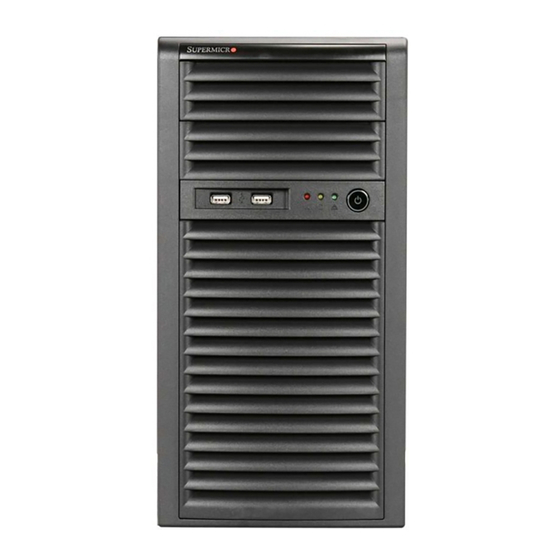
Chapter 1 Introduction Overview Supermicro’s SC731 chassis features a unique and highly-optimized design, allow- ing most configuration of the chassis to be accomplished without tools or screws. The chassis is equipped with high-efficiency power supply. High-performance fans provide ample optimized cooling for FB-DIMM memory modules, and four hot-swap drive bays offer maximum storage capacity. - Page 8 SC731 Chassis Manual SC731i-300B Chassis Power Model I/O Slots Supply 4x 3.5" 300W 2x 5.25" 4x FF High- SC731i-300B efficiency...
- Page 9 Super Micro Computer, Inc. 980 Rock Ave. San Jose, CA 95131 U.S.A. Tel: +1 (408) 503-8000 Fax: +1 (408) 503-8008 Email: marketing@supermicro.com (General Information) support@supermicro.com (Technical Support) Web Site: www.supermicro.com Europe Address: Super Micro Computer B.V. Het Sterrenbeeld 28, 5215 ML...
-
Page 10: Returning Merchandise For Service
For faster service, RMA authorizations may be requested online (http://www.super- micro.com/support/rma/). Whenever possible, repack the chassis in the original Supermicro carton, using the original packaging material. If these are no longer available, be sure to pack the chassis securely, using packaging material to surround the chassis so that it does not shift within the carton and become damaged during shipping. -
Page 11: Chapter 2 System Safety
Chapter 2: System Safety Chapter 2 System Safety Overview This chapter provides a quick setup checklist to get your chassis up and running. Following the steps in the order given should enable you to have your chassis setup and operational within a minimal amount of time. This quick setup assumes that you are an experienced technician, famailiar with common concepts and terminology. -
Page 12: General Safety Precautions
SC731 Chassis Manual and optical device drives. When disconnecting the power, you should first power down the system with the operating system and then unplug the power cords from all the power supply modules in the system. • When working around exposed electrical circuits, another person who is fa- miliar with the power-off controls should be nearby to switch off the power, if necessary. -
Page 13: System Safety
Chapter 2: System Safety • Remove any jewelry or metal objects from your body, which are excellent metal conductors that can create short circuits and harm you if they come into contact with printed circuit boards or areas where power is present. •... - Page 14 SC731 Chassis Manual Notes...
-
Page 15: Chapter 3 System Interface
Chapter 3 System Interface Chapter 3 System Interface Overview There are several LEDs on the control panel as well as others on the drive carriers to keep you constantly informed of the overall status of the system as well as the activity and health of specific components. -
Page 16: Control Panel Buttons
SC731 Chassis Manual Control Panel Buttons Power: The main power button is used to apply or remove power from the power supply to the system. When the power is on, the power button will be lighted by a blue LED. Turning off the system power with this button will cause the blue LED to turn off and will remove the main power, but will keep standby power supplied to the system. - Page 17 Chapter 3 System Interface Overheat/Fan Fail When Flashing: This LED indicates a fan failure. When Continuously On (not flashing): This LED indicates an overheat condi- tion caused by cables obstructing the airflow in the system or the ambient room temperature being too warm. Correcting an Overheat/Fan Fail Condition Check the routing of the cables and move any cables the restrict airflow.
- Page 18 SC731 Chassis Manual Notes...
-
Page 19: Chapter 4 Chassis Setup And Maintenance
Chapter 4: Chassis Setup and Maintenance Chapter 4 Chassis Setup and Maintenance Overview This chapter covers the steps required to install components and perform main- tenance on the chassis. Most components of the SC731 do not require tools or screws to set them up. Those components which must be secured with screws require only a Phillips screwdriver. -
Page 20: Removing The Chassis Cover
SC731 Chassis Manual Removing the Chassis Cover Cover Handle (B) Slide Tab A Toward Handle B Release Tab (A) Figure 4-1: Removing the Chassis Cover Removing the Chassis Cover Push the power button to turn off the power to the system. Disconnect the chassis from any power source. -
Page 21: Rotating The Hard Drive Cage
Chapter 4: Chassis Setup and Maintenance Rotating the Hard Drive Cage Release Tab (A) HDD Cage (B) Figure 4-2: Rotating the Hard Drive Cage In order to access and install components in the chassis interior, it is necessary to rotate the hard drive cage. This will provide sufficient room to install and configure the chassis components. -
Page 22: Removing And Installing Hard Drives
SC731 Chassis Manual Removing and Installing Hard Drives Release Tabs Figure 4-3: Removing the Hard Drive Carrier from the Hard Drive Cage The SC731 chassis must be powered-down before hard drives can be removed from the hard drive carriers. Removing and Installing Hard Drives Disconnect the chassis from any power source. - Page 23 Chapter 4: Chassis Setup and Maintenance Figure 4-4: Removing the Hard Drive from the Hard Drive Carrier If a hard drive is already present, remove it by carefully pulling the sides of the hard drive carrier outward. Remove the hard drive from the hard drive carrier.
- Page 24 SC731 Chassis Manual Optional Screws Figure 4-5: Installing the Hard Drive Carrier into the Hard Drive Cage Insert the new hard drive into the hard drive carrier. Insert the hard drive carrier into the hard drive cage, sliding it towards the back of the the hard drive cage until it clicks into a locked position.
-
Page 25: Installing The I/O Shield And Motherboard
Chapter 4: Chassis Setup and Maintenance Installing the I/O Shield and Motherboard I/O Shield Figure 4-6: I/O Shield Placement I/O Shield An I/O shield holds the motherboard ports in place. Install the I/O shield before you install the motherboard. The SC731 supports a Micro ATX motherboard, which is sold separately from the SC731 chassis and comes with an I/O shield specific to the Micro ATX motherboard. -
Page 26: Motherboard Installation
SC731 Chassis Manual Motherboard Installation Installing the Motherboard Review the documentation that came with your motherboard. Become familiar with component placement, requirements, precautions, and cable connec- tions. Disconnect the chassis from any power source. Rotate the hard drive cage 90 degrees outward, as described in the previous section, Rotating the Hard Drive Cage. -
Page 27: Installing An Optical Device
Chapter 4: Chassis Setup and Maintenance Installing an Optical Device The SC731 chassis has two optical device slots, which support up to two optional devices, such as DVD-ROM drives. Installing an Optical Device Remove the front bezel from the chassis by lifting it upwards from the bottom, and pulling off the front of the chassis. -
Page 28: Installing Add-On And Expansion Cards
SC731 Chassis Manual Installing Add-on and Expansion Cards Release Latch (A) Add-on/Expansion Card Slots Protective Bracket (B) Figure 4-9: Locating the Add-on Card Installation Components Add-on Card/Expansion Slot Setup The SC731 chassis includes slots for add-on cards and expansion cards. The number of cards you can use depends on your chassis model and motherboard model. -
Page 29: Long Add-On/Expansion Card Setup
Chapter 4: Chassis Setup and Maintenance Long Card Holders (A) Figure 4-10: Installing a Long Add-on/Expansion Card Long Add-on/Expansion Card Setup The SC731 chassis includes clips to accomodate the use of long-length add-on cards. These clips support and stabilize the long cards, preventing them from con- tacting any undesired surfaces. -
Page 30: Installing The System Fan
SC731 Chassis Manual Installing the System Fan Figure 4-11: Installing the System Fan The SC731 includes a super quiet system fan that provides cooling for the chassis. No tools or screws are required to install the system fan. Installing the System Fan Disconnect all power to the chassis. -
Page 31: Installing The Front Bezel
Chapter 4: Chassis Setup and Maintenance Installing the Front Bezel Front Bezel Installation Remove the dummy cover (A) for optical device from the front bezel. Install the front bezel onto the front of the chassis to complete the installation Remove the Dummy Cover (A) Figure 4-12: Installing the Front Bezel 4-13... -
Page 32: 4-10 Power Supply
SC731 Chassis Manual 4-10 Power Supply The SC731 chassis includes a 300 Watt power supply. In the unlikely event that it becomes necessary to replace the power supply, follow the instructions below. Power Supply Figure 4-13: Removing the Power Supply Changing the Power Supply Disconnect the chassis from any power source. -
Page 33: Appendix A Cables, Screws, And Other Accessories
This appendix lists the supported cables for the SC731 chassis. It only includes the most commonly used components and configurations. For more compatible cables, refer to the manufacturer of the motherboard and our Web site at: www. supermicro.com. A-2 Cables Included with SC731 Chassis SC731D-300B, SC731i-300B... - Page 34 SC731 Chassis Manual A-3 Chassis Screws The accessory box includes all the screws needed to set up your chassis. This section lists and describes the most commonly used screws. Your chassis may not require all of the parts listed. HARD DRIVE Flat head Pan head 6-32 x 5 mm...
-
Page 35: Appendix B Sc731 Power Supply Specifications
Appendix B: Power Supply Specifications Appendix B SC731 Power Supply Specifications This appendix lists power supply specifications for your chassis system. The SC731 chassis includes a power supply rated at 80 Plus Bronze Level. SC731D-300B, SC731i-300B 300W MFR Part # PWS-303-PQ Input 100 - 127/200~240Vac A/4A, 50 - 60Hz. - Page 36 SC731 Chassis Manual Disclaimer (cont.) The products sold by Supermicro are not intended for and will not be used in life sup- port systems, medical equipment, nuclear facilities or systems, aircraft, aircraft devices, aircraft/emergency communication devices or other critical systems whose failure to per- form be reasonably expected to result in significant injury or loss of life or catastrophic property damage.
Need help?
Do you have a question about the Supero SC731 Series and is the answer not in the manual?
Questions and answers