
Related Manuals for Supermicro SC745BAC-R1K28B2


Summary of Contents for Supermicro SC745BAC-R1K28B2
- Page 1 SC745 Chassis SC745BAC-R1K28B2 SC745BTQ-R1K28B SC745BTQ-R1K28B-SQ SC745TQ-R1200B SC745BAC-R1K23B SC745BAC-R1K23B-SQ SC745BTQ-R920B USER’S MANUAL Revision 1.1...
- Page 2 State of California, USA. The State of California, County of Santa Clara shall be the exclusive venue for the resolution of any such disputes. Supermicro's total liability for all claims will not exceed the price paid for the hardware product.
- Page 3 This document lists compatible parts available when this document was published. Refer to the Supermicro web site for updates on supported parts and configurations. This manual may be periodically updated without notice. Check the Supermicro website for possible updates.(http://www.supermicro.com). Notes Information on this and other chassis is available on the Supermicro website.
-
Page 4: Table Of Contents
Chassis SC745 User's Manual Contents Contacting Supermicro ......................6 Chapter 1 Introduction 1.1 Overview ..........................7 1.2 Unpacking the System ......................7 1.3 System Features ........................8 1.4 Chassis Features .........................9 Control Panel ........................9 Front Features ........................10 Rear Features ........................11 1.5 Where to Get Replacement Components ................12 1.6 Returning Merchandise for Service ..................12... - Page 5 Preface Chapter 3 Maintenance and Component Installation 3.1 Removing Power ........................24 3.2 Accessing the System ......................25 3.3 Chassis Components ......................26 Storage Drives ........................26 Drive Indicators ......................26 Installing the Internal Drives ..................27 Configuring the 5.25" Drive Bays ..................30 Additional Storage Drives in a Mobile Rack ..............33 Installing Expansion Cards....................35 System Cooling .........................36 Chassis Fans .........................36...
-
Page 6: Contacting Supermicro
Super Micro Computer, Inc. 980 Rock Ave. San Jose, CA 95131 U.S.A. Tel: +1 (408) 503-8000 Fax: +1 (408) 503-8008 Email: marketing@supermicro.com (General Information) support@supermicro.com (Technical Support) Website: www.supermicro.com Europe Address: Super Micro Computer B.V. Het Sterrenbeeld 28, 5215 ML... -
Page 7: Chapter 1 Introduction
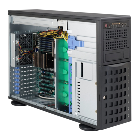
Chapter 1 Introduction Supermicro's SC745 chassis series is optimized for the latest Intel Xeon processor and is also compatible with previous generation Intel and AMD single/dual processor-based motherboards. Utilizing redundant, high-efficiency power supplies (95+%) and eight hot-swap 3.5" drive bays, this chassis offers reliable performance with problem-free maintenance. -
Page 8: System Features
Chassis SC745 User's Manual 1.3 System Features The following table provides you with an overview of the main features of the SC745. System Features Chassis SC745 Drives Bays Up to eight 2.5" or 3.5" internal hot-swap drive bays and three 5.25" external drive bays Cooling Three 8-cm, 4-pin PWM mid-chassis fans;... -
Page 9: Chassis Features
Chapter 1: Introduction 1.4 Chassis Features Control Panel Power switches and status LEDs are located on the control panel on the front of the chassis. Figure 1-1. Control Panel View Control Panel Features Item Feature Description The main power button is used to apply or remove power from the power supply to the server. -
Page 10: Front Features
Chassis SC745 User's Manual Front Features The SC745 is a tower chassis. See the illustration below for the features included on the front of the chassis. Figure 1-2. Chassis Front View Front Chassis Features Item Feature Description Front control panel with LEDs and buttons (see preceding page) Control Panel Peripheral Drive Bays Three 5.25"... -
Page 11: Rear Features
Chapter 1: Introduction Rear Features The illustration below shows the features included on the rear of the chassis. Figure 1-3. Chassis Rear View Rear Chassis Features Item Feature Description Power Supply Redundant, hot-swap power supplies I/O Back Panel Rear I/O ports (see Section 4.3) Two 8-cm exhaust fans Fans Expansion Slots... -
Page 12: Where To Get Replacement Components
For faster service, RMA authorizations may be requested online (http://www.supermicro.com/ support/rma/). Whenever possible, repack the chassis in the original Supermicro carton, using the original packaging material. If these are no longer available, be sure to pack the chassis securely, using packaging material to surround the chassis so that it does not shift within the carton and become damaged during shipping. -
Page 13: Chapter 2 Rack Mount Installation
Chapter 2 Rack Mount Installation Chapter 2 Rack Mount Installation 2.1 Overview This chapter provides instructions for preparing and mounting your chassis in a rack. By default, the chassis is shipped configured as a tower. The tower top cover and bottom feet must be removed to mount in a rack. -
Page 14: Server Precautions
Chassis SC745 User's Manual You should extend only one server or component at a time; extending two or more • simultaneously may cause the rack to become unstable. When initially installing the server to a rack, test that the rail locking tabs engage to prevent •... -
Page 15: Circuit Overloading
Chapter 2 Rack Mount Installation Circuit Overloading Consideration should be given to the connection of the equipment to the power supply circuitry and the effect that any possible overloading of circuits might have on overcurrent protection and power supply wiring. Appropriate consideration of equipment nameplate ratings should be used when addressing this concern. -
Page 16: Chassis Preparation
Chassis SC745 User's Manual 2.3 Chassis Preparation The chassis is shipped with the tower top cover and feet installed. Both must be removed for before installing the rails. Removing the Tower Top Cover 1. Locate the chassis cover lock (blue lever) at the rear of the chassis cover. 2. -
Page 17: Installing The Rails
Chapter 2 Rack Mount Installation 2.4 Installing the Rails There are a variety of rack units on the market, which may require a slightly different assembly procedure. Do not use a two post "telco" type rack. This rail set fits a rack between 26" and 35.9"... -
Page 18: Installing The Inner Rails
Chassis SC745 User's Manual Installing the Inner Rails Identify the left and right inner rails. 1. Attach the handles to the front sides of the chassis with three screws each. 2. Position the inner rails along the side of the chassis making sure the screw holes line up. 3. -
Page 19: Assembling And Installing The Outer Rails
Chapter 2 Rack Mount Installation Assembling and Installing the Outer Rails Each outer rail comes in three sections that require assembly before mounting onto the rack. 1. Find the outer rail mounting brackets in the chassis accessory box. A pair of long brackets for the rear of each rail •... -
Page 20: Installing The Server Into The Rack
Chassis SC745 User's Manual 2.5 Installing the Server into the Rack After attaching rails to both the chassis and the rack, slide the server into the rack. 1. Pull the middle rail out of the front of the outer rail and make sure that the ball bearing shuttle is locked at the front of the middle rail. -
Page 21: Removing The Chassis From The Rack
Chapter 2 Rack Mount Installation Removing the Chassis from the Rack Caution! It is dangerous for a single person to off-load the heavy chassis from the rack without assistance. Be sure to have sufficient assistance supporting the chassis when removing it from the rack. -
Page 22: Control Panel Orientation
Chassis SC745 User's Manual 2.6 Control Panel Orientation The server can be configured for either tower or server rack orientation. It is shipped in tower mode and can be immediately used as desktop server. To use it in a rack, rotate the module that contains the control panel and the three drive trays ( in Figure 2-6) 90 degrees. - Page 23 Chapter 2 Rack Mount Installation Rotating the Control Panel/Drive Module for Rack Mounting 1. Power down the system and open the chassis cover. 2. Disconnect any cables from the back of the Control Panel/Drive Module. 3. Push the module release lever to unlock the module. Control Panel/ Drive Module in Rack Mount...
-
Page 24: Chapter 3 Maintenance And Component Installation
Chassis SC745 User's Manual Chapter 3 Maintenance and Component Installation This chapter provides instructions on installing and replacing main system components. To assure compatibility, only use components that match the specifications or part numbers given. Installation or replacement of most components require that power first be removed from the system. -
Page 25: Accessing The System
Chapter 3: Maintenance and Component Installation 3.2 Accessing the System The chassis offers a removable side cover (top, if rack mounted) which allows access to the internal components. Removing the Side Cover 1. Locate the latch on the cover, depress where it says "push," then lift the latch to release the cover. -
Page 26: Chassis Components
2.5" drives with a bracket. Or two 5.25" bays can be replaced by an optional enclosure called a mobile rack that houses eight hot-swap 2.5" drives. Additional cables are also required. Note: Enterprise level hard disk drives are recommended for use in Supermicro chassis and servers. For information on recommended HDDs, visit the Supermicro website at http://www. -
Page 27: Installing The Internal Drives
Chapter 3: Maintenance and Component Installation Installing the Internal Drives Removing a Hot-Swap Drive Carrier 1. Open the front bezel then push the release button located beside the drive LEDs. 2. Swing the handle fully out and then use it to pull the unit straight out. Note: Your operating system must have RAID support to enable the hot-swap capability of the SATA drives. - Page 28 2. Remove the 2.5" drive from the tray. Figure 3-4. Removing a 2.5" Drive from the Carrier Note: Enterprise level hard disk drives are recommended for use in Supermicro chassis and servers. For information on recommended HDDs, visit the Supermicro website at http://www.
- Page 29 Chapter 3: Maintenance and Component Installation Removing the 2.5" Converter Bracket 1. Remove the screws from the drive carrier. 2. Remove the 2-in-1 converter bracket as shown below. Figure 3-5. Removing the Converter Bracket Installing a 3.5" Drive 1. Remove the screws from the drive carrier. 2.
-
Page 30: Configuring The 5.25" Drive Bays
Chassis SC745 User's Manual Configuring the 5.25" Drive Bays The control panel/drive module includes three 5.25" drive bays under the front control panel. It can be set up in a variety of configurations to suit the user's needs. • Up to three 5.25" peripheral drives, such as a DVD drive One or two additional fixed SATA, SAS or solid state drives in a single tray •... - Page 31 Chapter 3: Maintenance and Component Installation Installing a Storage Drive into a 5.25" Tray One 3.5" drive, or two 2.5" drives with an optional bracket (pn MCP-220-00044-0N) can be installed. An optional expansion card and cables are also required. 1. Remove the tray from the drive bay. 2.
- Page 32 Chassis SC745 User's Manual Installing a 5.25" Peripheral Device An optional peripheral device such as a DVD drive can be installed in a 5.25" bay. 1. Remove the tray from the drive bay. 2. Re-use the side rails from the tray and install them onto the peripheral device. Drive Tray Side Rails Figure 3-9.
-
Page 33: Additional Storage Drives In A Mobile Rack
Chapter 3: Maintenance and Component Installation Additional Storage Drives in a Mobile Rack The chassis accepts a Supermicro mobile rack (pn CSE-M28SABP) in place of two 5.25" bays. This adds eight hot-swap 2.5" SAS or SATA drives. An optional expansion card and cables are also required. - Page 34 Chassis SC745 User's Manual Rail Figure 3-11. Mobile Rack with Drive Tray Rails 3. Install a drive tray rail onto each side of the mobile rack. Make sure the arrow on the rail points toward the front of the chassis. 4.
-
Page 35: Installing Expansion Cards
Chapter 3: Maintenance and Component Installation Installing Expansion Cards The system can accommodate six PCIe cards. The chassis has seven slots, but the slot nearest the chassis top is not supported by this motherboard. Expansion Card Chassis Slots Figure 3-12. PCI Slots Installing an Expansion Card 1. -
Page 36: System Cooling
Chassis SC745 User's Manual System Cooling Three 8-cm fans located in the center of the chassis provide cooling airflow while two 8-cm exhaust fans at the rear of the chassis expel hot air. (The -SQ models have two 8-cm fans and one 9-cm fan.) The chassis is also fitted with an air shroud to concentrate the flow of cooling air over the areas of highest generated heat. -
Page 37: Air Shroud
Chapter 3: Maintenance and Component Installation Air Shroud Air shrouds concentrate airflow to maximize fan efficiency. It covers the processors and heatsinks. Installing the Air Shroud The air shroud fits behind the two fans closest to the power supply. Align the pins and press the air shroud into the chassis. -
Page 38: Power Supply
The hot-swap capability of the power supply modules allows you to replace the failed module without powering down the system. Replacement units can be ordered directly from Supermicro (see contact information in the Preface). -
Page 39: Removing The Front Bezel
Chapter 3: Maintenance and Component Installation Replacing the Power Supply You do not need to shut down the system to replace a power supply module. 1. Unplug the AC power cord from the failed power supply module. 2. Push the release tab on the power module to the side to unlock it then grasp the handle to pull it from the chassis. -
Page 40: Appendix A Power Supply Specifications
Chassis SC745 User's Manual Appendix A Power Supply Specifications This appendix lists power supply specifications for your chassis system. 1280W (Redundant) MFR Part # PWS-1K28P-SQ 1000W Output @ 100-140V, 12-8A, 50-60Hz AC Input 1280W Output @ 180-240V, 8-6A, 50-60Hz 1000W: +12V/83A; +5Vsb/4A DC Output 1280W: +12V/106.7A, +5Vsb/4A 1200W (Redundant) -
Page 41: Appendix B Standardized Warning Statements For Ac Systems
Supermicro's Technical Support department for assistance. Only certified technicians should attempt to install or configure components. Read this appendix in its entirety before installing or configuring components in the Supermicro chassis. These warnings may also be found on our website at http://www.supermicro.com/about/... - Page 42 Appendix B: Standardized Warning Statements Warnung WICHTIGE SICHERHEITSHINWEISE Dieses Warnsymbol bedeutet Gefahr. Sie befinden sich in einer Situation, die zu Verletzungen führen kann. Machen Sie sich vor der Arbeit mit Geräten mit den Gefahren elektrischer Schaltungen und den üblichen Verfahren zur Vorbeugung vor Unfällen vertraut. Suchen Sie mit der am Ende jeder Warnung angegebenen Anweisungsnummer nach der jeweiligen Übersetzung in den übersetzten Sicherheitshinweisen, die zusammen mit diesem Gerät ausgeliefert wurden.
- Page 43 Chassis SC745 User's Manual . ٌ ا ك ً ف حالة و ٌ يك أى تتسبب ف اصابة جسذ ة ٌ هذا الزهز ع ٌ خطز !تحذ ز قبل أى تعول عىل أي هعذات،يك عىل علن بالوخاطز ال ا ٌجوة عي الذوائز ٍ...
- Page 44 Appendix B: Standardized Warning Statements Warnung Vor dem Anschließen des Systems an die Stromquelle die Installationsanweisungen lesen. ¡Advertencia! Lea las instrucciones de instalación antes de conectar el sistema a la red de alimentación. Attention Avant de brancher le système sur la source d'alimentation, consulter les directives d'installation. .יש...
- Page 45 Chassis SC745 User's Manual Warnung Dieses Produkt ist darauf angewiesen, dass im Gebäude ein Kurzschluss- bzw. Überstromschutz installiert ist. Stellen Sie sicher, dass der Nennwert der Schutzvorrichtung nicht mehr als: 250 V, 20 A beträgt. ¡Advertencia! Este equipo utiliza el sistema de protección contra cortocircuitos (o sobrecorrientes) del edificio.
- Page 46 Appendix B: Standardized Warning Statements Power Disconnection Warning Warning! The system must be disconnected from all sources of power and the power cord removed from the power supply module(s) before accessing the chassis interior to install or remove system components. 電源切断の警告...
- Page 47 Chassis SC745 User's Manual אזהרה מפני ניתוק חשמלי !אזהרה יש לנתק את המערכת מכל מקורות החשמל ויש להסיר את כבל החשמלי מהספק .לפני גישה לחלק הפנימי של המארז לצורך התקנת או הסרת רכיבים يجب فصم اننظاو من جميع مصادر انطاقت وإ ز انت سهك انكهرباء من وحدة امداد انطاقت...
- Page 48 Appendix B: Standardized Warning Statements Attention Il est vivement recommandé de confier l'installation, le remplacement et la maintenance de ces équipements à des personnels qualifiés et expérimentés. !אזהרה .צוות מוסמך בלבד רשאי להתקין, להחליף את הציוד או לתת שירות עבור הציוד واملدربيه...
- Page 49 Chassis SC745 User's Manual Warnung Diese Einheit ist zur Installation in Bereichen mit beschränktem Zutritt vorgesehen. Der Zutritt zu derartigen Bereichen ist nur mit einem Spezialwerkzeug, Schloss und Schlüssel oder einer sonstigen Sicherheitsvorkehrung möglich. ¡Advertencia! Esta unidad ha sido diseñada para instalación en áreas de acceso restringido. Sólo puede obtenerse acceso a una de estas áreas mediante la utilización de una herramienta especial, cerradura con llave u otro medio de seguridad.
- Page 50 Appendix B: Standardized Warning Statements Battery Handling Warning! There is the danger of explosion if the battery is replaced incorrectly. Replace the battery only with the same or equivalent type recommended by the manufacturer. Dispose of used batteries according to the manufacturer's instructions 電池の取り扱い...
- Page 51 Chassis SC745 User's Manual هناك خطر من انفجار يف حالة اسحبذال البطارية بطريقة غري صحيحة فعليل اسحبذال البطارية فقط بنفس النىع أو ما يعادلها مام أوصث به الرشمة املصنعة جخلص من البطاريات املسحعملة وفقا لحعليامت الرشمة الصانعة 경고! 배터리가 올바르게 교체되지 않으면 폭발의 위험이 있습니다. 기존 배터리와 동일하거나 제 조사에서...
- Page 52 Appendix B: Standardized Warning Statements ¡Advertencia! Puede que esta unidad tenga más de una conexión para fuentes de alimentación. Para cortar por completo el suministro de energía, deben desconectarse todas las conexiones. Attention Cette unité peut avoir plus d'une connexion d'alimentation. Pour supprimer toute tension et tout courant électrique de l'unité, toutes les connexions d'alimentation doivent être débranchées.
- Page 53 Chassis SC745 User's Manual Backplane Voltage Warning! Hazardous voltage or energy is present on the backplane when the system is operating. Use caution when servicing. バックプレーンの電圧 システムの稼働中は危険な電圧または電力が、 バックプレーン上にかかっています。 修理する際には注意く ださい。 警告 当系统正在进行时,背板上有很危险的电压或能量,进行维修时务必小心。 警告 當系統正在進行時,背板上有危險的電壓或能量,進行維修時務必小心。 Warnung Wenn das System in Betrieb ist, treten auf der Rückwandplatine gefährliche Spannungen oder Energien auf.
- Page 54 Appendix B: Standardized Warning Statements هناك خطز مه التيار الكهزبايئ أوالطاقة املىجىدة عىل اللىحة عندما يكىن النظام يعمل كه حذ ر ا عند خدمة هذا الجهاس 경고! 시스템이 동작 중일 때 후면판 (Backplane)에는 위험한 전압이나 에너지가 발생 합니다. 서비스 작업 시 주의하십시오. Waarschuwing Een gevaarlijke spanning of energie is aanwezig op de backplane wanneer het systeem in gebruik is.
- Page 55 Chassis SC745 User's Manual תיאום חוקי החשמל הארצי !אזהרה .התקנת הציוד חייבת להיות תואמת לחוקי החשמל המקומיים והארציים تركيب املعدات الكهربائية يجب أن ميتثل للقىاويه املحلية والىطىية املتعلقة بالكهرباء 경고! 현 지역 및 국가의 전기 규정에 따라 장비를 설치해야 합니다. Waarschuwing Bij installatie van de apparatuur moet worden voldaan aan de lokale en nationale elektriciteitsvoorschriften.
- Page 56 Appendix B: Standardized Warning Statements Attention La mise au rebut ou le recyclage de ce produit sont généralement soumis à des lois et/ou directives de respect de l'environnement. Renseignez-vous auprès de l'organisme compétent. סילוק המוצר !אזהרה .סילוק סופי של מוצר זה חייב להיות בהתאם להנחיות וחוקי המדינה التخلص...
- Page 57 Chassis SC745 User's Manual Warnung Gefährlich Bewegende Teile. Von den bewegenden Lüfterblätter fern halten. Die Lüfter drehen sich u. U. noch, wenn die Lüfterbaugruppe aus dem Chassis genommen wird. Halten Sie Finger, Schraubendreher und andere Gegenstände von den Öffnungen des Lüftergehäuses entfernt.
- Page 58 Verbindungskabeln, Stromkabeln und/oder Adapater, die Ihre örtlichen Sicherheitsstandards einhalten. Der Gebrauch von anderen Kabeln und Adapter können Fehlfunktionen oder Feuer verursachen. Die Richtlinien untersagen das Nutzen von UL oder CAS zertifizierten Kabeln (mit UL/CSA gekennzeichnet), an Geräten oder Produkten die nicht mit Supermicro gekennzeichnet sind.
- Page 59 .قيرح وأ لطع يف ببستي دق ىرخأ تالوحمو تالباك يأ مادختسا .ميلسلا سباقلاو لصوملا مجح لبق نم ةدمتعملا تالباكلا مادختسا تادعملاو ةيئابرهكلا ةزهجألل ةمالسلا نوناق رظحيUL وأCSA ( ةمالع لمحت يتلاوUL/CSA) لبق نم ةددحملاو ةينعملا تاجتنملا ريغ ىرخأ تادعم يأ عمSupermicro.
- Page 60 사항을 준수하여 제공되거나 지정된 연결 혹은 구매 케이블, 전원 케이블 및 AC 어댑터를 사용하십시오. 다른 케이블이나 어댑터를 사용하면 오작동이나 화재가 발생할 수 있습니다. 전기 용품 안전법은 UL 또는 CSA 인증 케이블 (코드에 UL / CSA가 표시된 케이블)을 Supermicro 가 지정한 제품 이외의 전기 장치에 사용하는 것을 금지합니다. Stroomkabel en AC-Adapter...
-
Page 61: Appendix C Bpn-Sas-743Tq Backplane Specifications
C-2 Version Information This manual reflects BPN-SAS-743TQ, Revision 3.00, the most current release available at the time of publication. Refer to the Supermicro Web site at www.supermicro.com for the latest updates, compatible parts and supported configurations. All images and layouts shown in this guide are based upon the latest PCB revision available... - Page 62 Chassis SC745 User's Manual C-3 Rear Connectors, Jumpers, and Indicators Rear Connector Locations The following connectors are on the side of the backplane that faces the rear of the chassis. They are identified by silkscreen labels. M 8 7 M 9 6 M 8 6 M 9 7 UPER...
- Page 63 Appendix C: BPN-SAS-743TQ Backplane Specifications Rear Connectors and Pin Definitions #1. and #2. JTAG Connector and Upgrade Connectors The JTAG and Upgrade connectors, designated JP47 and JP46, are used for diagnostic purposes. These connectors should be used by a certified and experienced technician. #3.
- Page 64 Chassis SC745 User's Manual SAS Port Connections in I C and SGPIO Settings Use the following chart when connecting this backplane. If you connect the SAS ports out of order, you will not able to easily identify drives using the LED function. SAS Port Connections in I C and SGPIO Settings Port #...
- Page 65 Appendix C: BPN-SAS-743TQ Backplane Specifications Jumper Settings Jumper Jumper Settings Note Open: Enabled Buzzer reset* JP18 Closed: Disabled Open: Default MG9072 chip reset JP29 Closed: Reset *The buzzer sound indicates that a condition requiring immediate attention has occurred. The buzzer alarm is triggered by the following conditions: hard drive failure, fan failure, or system temperature over 45º...
- Page 66 Chassis SC745 User's Manual Rear LED Indicators M 8 7 M 9 6 M 8 6 M 9 7 UPER SAS743TQ M M 3 M M 2 REV 3.00 OH/Drive Fail LED +12V +12V GND +5V Figure C-3. Rear LEDs Front Panel LEDs State Specification...
- Page 67 Appendix C: BPN-SAS-743TQ Backplane Specifications C-4 Front Connectors and Indicators SAS #0 SAS #1 SAS #2 SAS #3 SAS #4 SAS #5 SAS #6 SAS #7 Figure C-4. Front Connectors and LEDs Drive Connectors and LED Indicators HDD Activity LED HDD Failure LED Drive Number Label...
-
Page 68: Appendix D Bpn-Sas3-743A Backplane Specifications
D-2 Version Information This manual reflects BPN-SAS3-743A, Revision 1.00, the most current release available at the time of publication. Refer to the Supermicro Web site at www.supermicro.com for the latest updates, compatible parts and supported configurations. All images and layouts shown in this guide are based upon the latest PCB revision available... - Page 69 Appendix D: BPN-SAS3-743A Backplane Specifications D-3 Rear Connectors, Jumpers, and Indicators Rear Connector Locations The following connectors are on the side of the backplane that faces the rear of the chassis. They are identified by silkscreen labels. Figure D-1. Rear Connectors 1.
- Page 70 Chassis SC745 User's Manual Rear Connectors and Pin Definitions #1. CPLD Chip The CPLD is an enclosure management chip that supports the SGPIO and LED management. #2. JTAG Connector The JTAG connector, designated J16, is used for diagnostic purposes. This connector should not be used as it is for internal testing only.
- Page 71 Appendix D: BPN-SAS3-743A Backplane Specifications Rear Jumpers and Pin Definitions The jumpers are used for internal texting only. ACTLED Figure D-2. Rear Jumpers Jumper Settings Jumper Jumper Settings Note 2-3: Default This is used for internal testing only. 1-2: Default This is used for internal testing only.
- Page 72 Chassis SC745 User's Manual D-4 Front Connectors and Indicators SAS #0 SAS #1 SAS #2 SAS #3 SAS #4 SAS #5 SAS #6 SAS #7 ACT#0 FAIL#0 Figure D-3. Front Connectors and LEDs Drive Connectors and LED Indicators HDD Activity LED HDD Failure LED Drive Number Label...
Need help?
Do you have a question about the SC745BAC-R1K28B2 and is the answer not in the manual?
Questions and answers