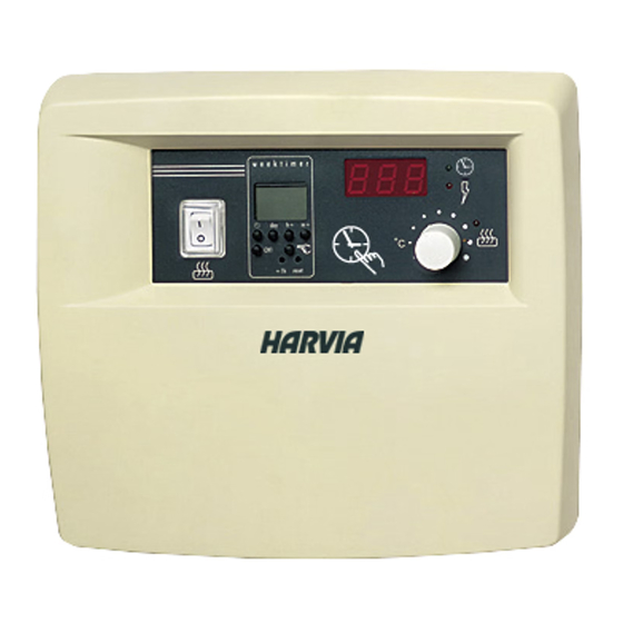
Summary of Contents for Harvia C260
- Page 1 C260 Control unit Ovladaci jednotka Finskasauna.cz Slepá 15 Brno 602 00 Tel. 606 646 269 Harvia Oy PL 12 40951 Muurame Finland www.harvia.fi 19012005...
-
Page 2: Table Of Contents
OBSAH CONTENTS 1. CONTROL UNIT C260 ..........3 1. Ovládací jednotka C260 ..........3 1.1. Technical data ..........3 1.1. Technické informace ..........3 2. C260VKK CONTROL UNIT: INSTRUCTIONS FOR USE ... 4 2.1. Main Switch (1) ..........4 2. C260VKK ovládací jednotka: instrukce pro užití ..4 2.2. -
Page 3: Control Unit C260
Jednotka s oznacenim C260-20 je urcena pro výkony kW of power output (for instance two 11 kW heaters or 10,5 - 22 Kw s jistice 16A a C260-34 je pro výkony one 20 kW heater). The more powerful power units that 26 - 34 Kw a jistice jsou 25 A. -
Page 4: C260Vkk Control Unit: Instructions For Use
2. C260VKK CONTROL UNIT: 2. C260VKK ovládací jednotka INSTRUCTIONS FOR USE Instrukce pro užití Pred zapnutim kamen zkontrolujte jestli Before you switch the heater on check always that there aren’t any things over the heater or in the near u kamen nejsou zadne nevhodne predmety distance of the heater. -
Page 5: Weekly Timer (Weektimer) (2)
Obrázek 1. Ovládací jednotka: ovládací prvky a indikacní kontrolky Figure 1. Control unit: switches and indicator lights The main switch functions like an Hlavni vypinac funguje jako emergency OFF switch as power to the nouzovy vypinac a kamna se heater can be disconnected by selecting odpoji prepnutim do polohy OFF position “0“... -
Page 6: Setting The Weekly Timer To Real Time
2.2.2.Setting the Weekly Timer to Real 2.2.2. Nastaveni tydenniho casovace do do realneho rezimu. Time keep the [clock] -button in the down • Tlacítky [h +] a [H ÿ ] nastahujete celé hodiny. position the whole time. Pokud podržíte tlacítko [h +] zpusobí to, že press the hours button [h+] to set the •... - Page 7 The following selection modes are • Tlacítkem [den] nastavujete vybrané dny sepnutí: available with the [day] -button: • 1 2 3 4 5 6 7 = (Po, Út, St, ÿt, Pá, So a Ne) 1 2 3 4 5 6 7= •...
-
Page 8: Manual Control Operations With The Weekly Timer
2.2.4. Manual Control Operations with the 2.2.4. Manualni ovladani operaci Weekly Timer Tydenni casovac Použitím tlacítka manual Using the weekly timer’s [manual] - button you can turn the heater on instantly as with mužete týdením casovacem manual button 3. The appropriate symbol ovládat kamna rucne jako s will appear in the screen to show that the manuálním tl. - Page 9 Changing Program Timings Zmena v programu nacasovani using the [Ch] -program button scan the • - pomocí tlacitka /CH/ budete provadet screen for the program timing to be zmeny v casovani. Pro nastaveni casu changed. The time and day settings a dni se musite pohybovat v menu stejne that appear in the screen can be altered using the appropriate...
-
Page 10: Manual Switch (3)
2.3. Manual Switch (3) 2.3. Manualni owladani (3) 2.3.1. Heater On Instantly 2.3.1. Okamzite sepnuti kamen If you press the manual switch (3) once briefly (while Kdyz stisknete kratce tlacitko manualniho ovladani (3 ) the control unit is switched on), the heater comes on ( kdyz je jednotka zapnuta hlavnim vypinacem ) immediately for half an hour;... -
Page 11: Indicator Light, Green (7)
2.7. Indicator Light, Green (7) 2.7. Kontrolka zelena (7) When indicator light 7 is on, the screen displays the Kdyz sviti zelena kontrolka (7) na na displeji, time set for the heater to be on. nacasovani pro kamna je zaple. 2.8. -
Page 12: Fastening The Device To The Wall
3.1.2. Fastening the Device to the Wall 3.1.2. Wandbefestigung There are holes for three (3) screws in the base plate, Jednotku na zed prichytte dle obrazku 26. for fastening the unit to the wall. If necessary, drill a hole in the wooden wall using a 2.5 mm bit. If you have to fasten the device to a stone wall, drill a 6 mm hole for a Rawlplug to its complete length. -
Page 13: Altering The Basic Settings Of The Control Unit
3.1.4. Altering the Basic Settings of the Control Unit 3.1.4. Alternativni nastaveni v ovladacim panelu The maximum times you can set the heater to come on Maximalni cas ktery lze nastavit pro provoz kamen je from the control unit are : 6 h, 12 h, 18 h or 5h, 12h, 18h nebo nepretrzity provoz. -
Page 14: Installing The Thermostat's Sensor Box
“Er1“, “Er2“ or “Er3“. See 1. na strop na zed na zed cidlo cidlo cidlo Figure 30. Installation of control unit (C260) sensor box and of the heaters L20-L33 obrazek 30. Instalace cidla pro kamna L20-L33... -
Page 15: Installing The Power Unit C260K
Rozvadece a pojistky zasobuji elektrinou kamna pomoci The connection is shown in the 2 kabelu. Zapojeni je na obr. 32. diagram.(Fig. 32) C260-20 K1: contactor 63A K2 and K3:contactor 25A for Fig. 31. Installation of the control C260-20... - Page 16 K1: 63A F1, F2 (16A) MAX 22 kW F1, F2 (25A): K2, K3: 25A MAX 34 kW CONTACTORS FUSES POWER UNIT Svorkovnice Pojistky Silova cast 5 7 1 3 Group I Group II Skupi n a 1 Skup 2 F1 F2 F1 F2 F1 F2 Figure 33.


Need help?
Do you have a question about the C260 and is the answer not in the manual?
Questions and answers