Table of Contents
Advertisement
Quick Links
Advertisement
Table of Contents

Related Manuals for Harvia SIGMA COMBI CS110C


Summary of Contents for Harvia SIGMA COMBI CS110C
- Page 1 HARVIA SIGMA COMBI CS110C Ohjauskeskus Styrenhet Control unit Steuergerät Пульт управления Juhtimiskeskus Centre de contrôle Sterownik Centralina di controllo Адрес: ООО «Харвия РУС». 196084, г. Санкт-Петербург, ул. Заставская, дом 7 E-mail: regionlog12@mail.ru 02052016/ZVR-941...
-
Page 2: Table Of Contents
Congratulations on making an excellent choice! Wir beglückwünschen Sie zu Ihrer guten Wahl! CONTENTS INHALT 1. HARVIA SIGMA COMBI ..........21 1. HARVIA SIGMA COMBI ..........21 1.1. General ............21 1.1. Allgemeines ............21 1.2. Technical Data ..........21 1.2. -
Page 3: Harvia Sigma Combi
1. HARVIA SIGMA COMBI 1.1. General 1.1. Allgemeines The purpose of the Harvia Sigma Combi control unit Der Zweck des Steuergeräts Harvia Sigma Combi is to control an electric sauna heater and steamer, liegt darin, einen elektrischen Saunaofen nebst Ver-... -
Page 4: Troubleshooting
temperature and relative humidity. rücksetzbaren Überhitzungsschutz und einem Weight 175 g with leads (ca 4 m) NTC-Thermistor zur Temperaturerfassung aus- • Dimensions: 51 mm x 73 mm x 27 mm gestattet (22 kΩ/T=25 °C). • Der Feuchtigkeitsfühler WX325 misst Tempera- •... -
Page 5: Instructions For Use
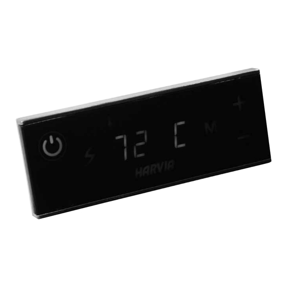
2. INSTRUCTIONS FOR USE 2. BEDIENUNGSANLEITUNG 2.1. Using the Heater and the Steamer 2.1. Verwendung des Ofens und des Verdampfers When the control unit is connected to the pow- Wenn das Steuergerät an die Stromversorgung an- er supply and the main switch (see figure 1) is geschlossen ist und der Hauptschalter (siehe Ab- switched on, the control unit is in standby mode bildung 1) betätigt wird, befindet sich das Steuer-... -
Page 6: Using Accessories
The programmed temperature and humidity values Die programmierten Temperatur- und Luftfeuch- and all values of additional settings are stored in tigkeitswerte und alle weiteren Einstellungswerte memory and will also apply when the devices are werden gespeichert und auch beim nächsten Ein- switched on next time. - Page 7 Die eingestellte Temperatur wird zuerst 80 C The set temperature is displayed first, 80 C angezeigt, danach schaltet die Anzeige after which the display switches to zur aktuellen Temperatur in der Sauna- current sauna room temperature. The kabine um. Der Ofen beginnt sofort zu 22 C 22 C heater starts heating immediately.
- Page 8 Press button 5. Drücken Sie die Taste 5. Remaining on-time. The minimum value Verbleibende Einschaltzeit. Der Mindest- 4:00 4:00 is 10 minutes. The maximum value can wert beträgt 10 Minuten. Der Maximal- be set from additional settings (1–12 h). wert kann unter „Weitere Einstellungen“ festgelegt werden (1–12 h).
- Page 9 Memory for power failures. You can Speicher für Stromausfälle. Sie können SET3 SET3 choose how the device behaves after a festlegen, wie sich das Gerät nach einem break in electricity. Stromausfall verhalten soll. ON: The system will start again. ON (Ein): Das System wird neu •...
-
Page 10: Instructions For Installation
3. INSTRUCTIONS FOR INSTALLATION 3. INSTALLATIONSANLEITUNG The electrical connections of the control unit Die elektrischen Anschlüsse des Steuergeräts dür- may only be made by an authorised, professional fen nur von einem autorisierten, geschulten Elektri- electrician and in accordance with the current ker unter Beachtung der aktuell gültigen Vorschrif- regulations. -
Page 11: Installing The Power Unit
3.2. Installing the Power Unit 3.2. Montage der Leistungseinheit Install the power unit to a wall outside the sauna Bringen Sie die Leistungseinheit an einem trocke- room, in a dry place with an ambient temperature nen Ort außerhalb der Saunakabine mit einer Um- of >0 ºC. - Page 12 Heater Fuses (A) Wire sizes (mm Ofen Sicherungen Stärken von Kabeln (mm H07RN-F H07RN-F K11GS 3 x 10 3 x 1,5 6 x 1,5 6 x 1,5 5 x 2,5 5 x 2,5 K13.5GS 3 x 16 3 x 1,5 6 x 1,5 6 x 1,5 5 x 4,0 5 x 2,5...
-
Page 14: Installing The Temperature Sensor
3.3. Installing the Temperature Sensor 3.3. Montage des Temperaturfühlers Check the correct location for the temperature sen- Überprüfen Sie den richtigen Standort des Tempe- sor from the heater’s instructions for installation raturfühlers nach den Gebrauchs- und Montagean- and use. leitungen des Ofens. Wall-mounted heaters (see figure 6) Öfen mit Wandbefestigung (Abbildung 6) Fasten the temperature sensor on the wall... -
Page 15: Installing The Humidity Sensor
3.4. Installing the Humidity Sensor 3.4. Montage des Feuchtigkeitsfühlers Fasten the humidity sensor on the wall as far from Bringen Sie den Feuchtigkeitsfühler so weit wie the heater as possible and at a distance of 500– möglich vom Ofen entfernt an der Wand an, in ei- 700 mm from the ceiling. -
Page 16: Resetting The Overheat Protector
WX232 360° 180° Figure 9. Reset button of the overheat protector Abbildung 9. Rückstellknopf des Überhitzungsschutzes Figure 8. Sensor’s minimum distance from an air vent Abbildung 8. Mindestabstand des Fühlers zu Luftschlitzen 3.5. Resetting the Overheat Protector 3.5. Zurückstellen der Überhitzungsschutzes The sensor box ( ) contains a temperature Das Fühlergehäuse (WX232) enthält einen Tempe-...
Need help?
Do you have a question about the SIGMA COMBI CS110C and is the answer not in the manual?
Questions and answers