Table of Contents
Advertisement
Quick Links
Advertisement
Table of Contents

Related Manuals for Harvia CF9


Summary of Contents for Harvia CF9
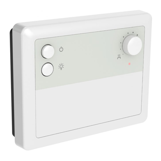
- Page 1 Control unit Steuergerät 01042016/ZCF-113...
-
Page 2: Table Of Contents
3.3. Installation des Fühlergehäuses ......6 3.4. Electrical connections .......... 7 3.4. Schaltverbindungen ..........7 3.5. Service instructions for the CF9 control unit ... 7 3.5. Wartungsanleitung für das Steuergerät CF9 .... 7 4. SpARe pARtS ............8 4. eRSAtZteILe ............. 8... -
Page 3: Control Unit Cf9
1. SteUeRGeRÄt CF9 1.1. General 1.1. Allgemeines The control unit CF9 is intended for the control of Das Steuergerät CF9 ist für die Steuerung drei- 3-stage sauna heaters (max. 9 kW) in family sau- phasigerelektrischer Öfen (max. 9 kW) in Privatsau- nas that do not have fixed control devices (3-stage nen ausgelegt, die nicht über eingebaute Regler ver-... - Page 4 temperature scale, testing is required to find the 3. temperaturregler desired temperature. Der Temperaturregler dient zur Einstellung der ge- Testing can begin from half way between the wünschten Saunatemperatur. Da der Regler nicht minimum and maximum position. When turning the über eine Temperaturskala verfügt, muss die ge- adjuster clockwise, the temperature rises, when it wünschte Temperatur durch Ausprobieren ermittelt...
-
Page 5: Instructions For Installing The Control Unit
3. InStRUCtIonS FoR InStALLInG 3. InStALLAtIonSAnLeItUnG FÜR tHe ContRoL UnIt DAS SteUeRGeRÄt The control unit is installed outside the sauna room, Das Steuergerät wird an einem trockenen Ort außer- in a dryplace (ambient temperature >+0ºC). halb der Saunakabine (Betriebstemperatur >+0ºC). note! the control unit should not be embedded ACHtUnG! Das Steuergerät darf nicht in die within the wall structure. -
Page 6: The Installation Of The Sensor Box
die gleiche wie oben, mit dem Unterschied, dass diese Schrauben so weit wie möglich eingedreht werden. Siehe Abb. 4. 3.3. the installation of the sensor box 3.3. Installation des Fühlergehäuses To control wall-mounted heaters with the control Zur Steuerung von Saunaöfen mit Wandbefesti- unit, the sensor box connected to the unit should gung über das Steuergerät muss das an das Gerät be installed on the sauna wall above the heater on... -
Page 7: Electrical Connections
Sicherung für Beleuchtung T1AH Junction box <6–9 3 x 16 5 x 2,5 5 x 2,5 Klemmdose Figure 6. Electrical connections for the heaters, as well as for the control unit CF9 Abbildung 6. Elektroanschlüsse der Saunaöfen sowie des Steuergeräts CF9... -
Page 8: Spare Parts
thermostat sensor circuit faults ACHtUnG! eine defekte Sicherung muss ge- The components of the sensor box monitor the func- gen eine Sicherung desselben Widerstands ausge- tioning of the control unit. The temperature sensor tauscht werden. and the overheat protector are located in the sensor box.
Need help?
Do you have a question about the CF9 and is the answer not in the manual?
Questions and answers