hager 4500 Installation Instructions Manual
Mortise lock exit device
Hide thumbs
Also See for 4500:
- Installation instructions manual (12 pages) ,
- Electrical supplemental instructions (3 pages) ,
- Installation instructions (3 pages)

Subscribe to Our Youtube Channel
Related Manuals for hager 4500


Summary of Contents for hager 4500
-
Page 1: Installation Instructions
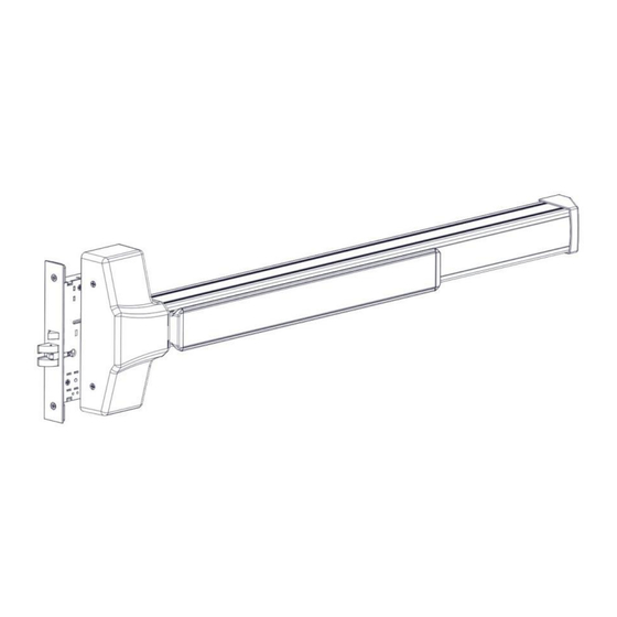
Mortise Lock Exit Device Installation Instructions I-ED01553 DEVICES COVERED IN THIS DOCUMENT: 4500 MORTISE LOCK EXIT DEVICE TOOLS REQUIRED Rev 4, Rev Date: 06/19/18 27390043 Page 1 of 10... - Page 2 Mortise Lock Exit Device Installation Instructions I-ED01553 END CAP BRACKET MORTISE STRIKE (PANIC-RATED) MORTISE LOCK EXIT DEVICE MORTISE LOCK BODY END CAP CHASSIS COVER MORTISE STRIKE (FIRE-RATED) Fasteners and Other Parts Included Qty. Purpose ¼”-20 x ¾” Pan Head Machine Screws Through-bolting to wood or metal doors or surface mounting to metal doors #12 x 1.25”...
- Page 3 2. PREPARE DOOR The Hager Exit device is designed to fit a door and frame prepared for a Mortise Lock per ANSI/BHMA A156.115-2016. The holes and cutouts specifically for the Hager Mortise Lock Exit Device are shown in the template T-ED01545 and in the Door Preparation Drawing S-ED01546.
- Page 4 Mortise Lock Exit Device Installation Instructions I-ED01553 4. SET OUTSIDE HANDING OF LOCK CASE (BE AND CE FUNCTIONS ONLY) Skip this step for NL and DT functions. There is a catch screw on each side of the lock body. For BE and CE functions a catch screw must be removed on the PULL side of the lock body.
- Page 5 Mortise Lock Exit Device Installation Instructions I-ED01553 6. INSTALL LOCK TO DOOR Install the lock in the door using the two supplied Wood/Metal combo screw. 7. INSTALL THE STRIKE IN THE FRAME Install the strike in the frame using the supplied #12 Wood/Metal Combination Screws. Rev 4, Rev Date: 06/19/18 27390043 Page 5 of 10...
- Page 6 Mortise Lock Exit Device Installation Instructions I-ED01553 8. INSTALL EXIT DEVICE (METAL DOORS ONLY) Remove the chassis cover from the exit device. Put the exit device up against the door. Make sure the Latch Finger on the exit device is inserted into the slot on the door and the mortise lock body and does not rub on the edges of the cutouts. Attach the exit device to the door with the supplied ¼-20 x 3/8”...
- Page 7 Mortise Lock Exit Device Installation Instructions I-ED01553 9. INSTALL END CAP Remove end cap from end cap bracket. Mark the hole locations by holding the end cap bracket against the door. Make sure the exit device is level before inserting the end cap bracket into the end of the exit device body. Mark and drill/tap holes. Install end cap bracket and end cap using supplied screws.
-
Page 8: Install Trim
Mortise Lock Exit Device Installation Instructions I-ED01553 11. HAND TRIM (NL AND DT FUNCTIONS ONLY) For handing the NL and DT trim there is no spring cage. Position the handle in the proper orientation and install the handing pin. 12. INSTALL TRIM Install the trim on the pull side of the door insuring that the handing pin is properly inserted into the lock body. - Page 9 Mortise Lock Exit Device Installation Instructions I-ED01553 14. INSTALL CYLINDER (NO TRIM – NL FUNCTION ONLY) Only the Night Latch function can be used with a cylinder only or cylinder by optional pull. Loosen the cylinder retaining screw to allow the cylinder to be threaded into the lock case.
- Page 10 Required hardware for cylinder dogging includes one (1) mortise cylinder, lengths 1-1/8”, 1-1/4” or 1-3/8” with a standard cam (0.723” [18mm] screw center to tip of cam); and one (1) Hager cylinder dogging kit (4926) which includes one (1) 11/32” [8.7mm] solid cylinder collar and cashbox nut.
Need help?
Do you have a question about the 4500 and is the answer not in the manual?
Questions and answers