Table of Contents
Advertisement
Available languages
Available languages
Quick Links
Advertisement
Chapters
Table of Contents

Subscribe to Our Youtube Channel
Related Manuals for ProLights Halupix


Summary of Contents for ProLights Halupix
- Page 1 HALUPIX LED MATRIX MANUALE UTENTE USER MANUAL IT - EN...
- Page 2 Music & Lights S.r.l. si riserva ogni diritto di elaborazione in qualsiasi forma delle presenti istruzioni per l’uso. La riproduzione - anche parziale - per propri scopi commerciali è vietata. Al fine di migliorare la qualità dei prodotti, la Music&Lights S.r.l. si riserva la facoltà di modificare, in qualunque momento e senza preavviso, le specifiche menzionate nel presente manuale di istruzioni.
-
Page 3: Table Of Contents
4 Manutenzione 4. 1 Manutenzione e pulizia del sistema ottico 4. 2 Sostituzione fusibile 4. 3 Risoluzione dei problemi Certificato di garanzia Contenuto dell'imballo: • HALUPIX • Staffa di fissaggio • Chiave a brugola • Cavo di alimentazione • Manuale utente... -
Page 4: Sicurezza
• Non attaccare all’unità dispositivi o accessori diversi dai prodotti della serie HALUPIX. • Non lasciare che il cavo di alimentazione venga a contatto con altri cavi! Maneggiare il cavo di alimen- tazione e tutte le connessioni con la rete, prestando particolare attenzione. -
Page 5: Informazioni Generali
(in materia di sicurezza) vigenti nel paese di utilizzo. • L’utente è responsabile del corretto posizionamento e funzionamento dell’HALUPIX. Music & Lights non si assume alcuna responsabilità per danni causati da un uso improprio o non corretta installazione di questo dispositivo. -
Page 6: Introduzione
è quello di un muro di LED, in grado di proiettare fasci di luce calda a lunga gittata distinguibili tra di loro, che superano di gran lunga la potenza dei tradizionali LEDwall. HALUPIX è una matrice di 7x7 LEDs CREE ad alta efficienza di dimensioni 50x50cm, con sistema di rigging modulare per costruire pareti di LEDs di qualsiasi forma o superficie. -
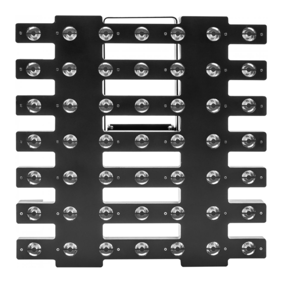
Page 7: Elementi Di Comando E Di Collegamento
HALUPIX 1.3 ELEMENTI DI COMANDO E DI COLLEGAMENTO Fig.1 1. STAFFA DI MONTAGGIO 6. HARDWARE per configurazioni verticali 2. MANOPOLA DI FISSAGGIO per la staffa di 7. Connettori DMX: montaggio DMX OUT (XLR a 3 poli): 3. PANNELLO DI CONTROLLO con display e 4... -
Page 8: Installazione
4. Assicurarsi che la struttura sia in grado di sostenere il peso dei moduli. 2.1 MONTAGGIO L’HALUPIX può essere collocato su un piano solido. Inoltre, grazie alle possibilità di fissaggio sulla doppia staffa (fig.2), l’unità può essere montata anche su una traversa. Per il fissaggio occorrono dei supporti ro- busti per il montaggio. -
Page 9: Congiunzione Orizzontale Dei Moduli
HALUPIX 2.2 CONGIUNZIONE ORIZZONTALE DEI MODULI Ogni modulo HALUPIX può essere facilmente congiunto orizzontalmente attraverso i due sistemi di giun- zione laterali integrati in ciascun modulo. Tali elementi di giunzione possono essere a scomparsa se non utilizzati. 1. Avvicinare e allineare l’elemento scorrevole del sistema di giunzione del modulo 1 con la scanalatura laterale del modulo 2 (fig.3). -
Page 10: Congiunzione Verticale Dei Moduli
HALUPIX 2.3 CONGIUNZIONE VERTICALE DEI MODULI Ogni modulo HALUPIX può essere facilmente congiunto verticalmente attraverso i due sistemi di giunzio- ne posti sulla parte superiore e inferiore di ciascun modulo. Tali elementi di giunzione possono essere a scomparsa se non utilizzati. -
Page 11: Funzioni E Impostazioni
Per spegnere l’HALUPIX, staccare la spina dalla presa di rete. Per maggiore comodità è consi- gliabile collegare l’unità con una presa comandata da un interruttore. 3.2 IMPOSTAZIONE BASE Il modulo HALUPIX dispone di un display LCD e 4 pulsanti per accesso alle funzioni del pannello di con- trollo (fig.5). MENU... -
Page 12: Struttura Menu
HALUPIX 3.3 STRUTTURA MENU MENU ð ð Auto Show Auto 0 Speed 0~100 ð Auto 1 Speed 0~100 ð Auto 2 Speed 0~100 ð Auto 3 Speed 0~100 ð Auto 4 Speed 0~100 ð Auto 5 Speed 0~100 ð Auto 6 Speed 0~100 ð... -
Page 13: Modalità Automatica
Nella modalità automatica l’unità è MASTER. 3.5 MODALITÀ MASTER/SLAVE Questa modalità consente di collegare in linea più unità HALUPIX senza un controller. La prima unità sarà impostata come master e le altre funzioneranno come slave con lo stesso effetto. • Premere il tasto MENU fino a quando sul display non appare [MASTER/SLAVE], quindi premere il tasto ENTER per confermare la scelta. -
Page 14: Modalità Dmx
3.7 CONFIGURAZIONI CANALI DMX L’HALUPIX dispone di 3 configurazioni dei canali DMX a cui si può accedere dal pannello di controllo. • Premere il tasto MENU fino a quando sul display non appare [DMX CHANNEL], quindi premere il tasto ENTER. -
Page 15: Collegamenti Della Linea Dmx
HALUPIX 3.10 COLLEGAMENTI DELLA LINEA DMX La connessione DMX è realizzata con connettori standard XLR. Utilizzare cavi schermati, 2 poli ritorti, con impedenza 120Ω e bassa capacità. Per il collegamento fare riferimento allo schema di connessione riportato di seguito: DMX - INPUT... -
Page 16: Canali Dmx
HALUPIX 3.12 CANALI DMX 5 CANALI 8 CANALI MODE MODE FUNCTION FUNCTION Value Value 5 Ch 8 Ch DIMMER DIMMER 0 - 100% 000 - 255 0 - 100% 000 - 255 STROBE STROBE No Function 000 - 010 No Function... - Page 17 HALUPIX MODE MODE FUNCTION FUNCTION Value Value 8 Ch 49 Ch GOBO SPEED WHITE 9 No function (stop) 000-010 0 - 100% 000 - 255 Gobo index 011-100 WHITE 10 No function 101-149 0 - 100% 000 - 255 Gobo speed (CW)
- Page 18 HALUPIX MODE MODE FUNCTION FUNCTION Value Value 54 Ch 54 Ch Auto 5 123 - 150 WHITE 5 Auto 6 151 - 178 0 - 100% 000 - 255 Auto 7 179 - 206 WHITE 6 Auto 8 207 - 234...
- Page 19 HALUPIX MODE MODE FUNCTION FUNCTION Value Value 57 Ch 57 Ch Diamond Exploder (gobo 6) 057-065 WHITE 9 2 Line Spinner (gobo 7) 066-074 0 - 100% 000 - 255 Triangle Spinner (gobo 8) 075-083 WHITE 10 Tri-Downer (gobo 9)
-
Page 20: Configurazione Static
255) si riscontra un effetto stroboscopico che procede da lento a veloce. 3.14 FUNZIONI DISPOSITIVO Per l’HALUPIX è possibile accedere alle seguenti funzioni dispositivo: Dimmer • Per entrare nella modalità dimmer e scegliere e simulare diverse curve dimming, premere il tasto MENU ripetutamente fino a quando sul display non compare [DIMMER MODE], quindi premere il tasto ENTER. -
Page 21: Impostazioni Ethernet
HALUPIX Fixture Hours Permette di visualizzare le ore di funzionamento del dispositivo. • Premere il tasto MENU ripetutamente fino a quando sul display non compare [INFORMATION]. • Premere il tasto ENTER per confermare. • Selezionare attraverso i tasti UP/DOWN [FIXTURE HOURS], quindi premere ENTER per confermare. -
Page 22: Manutenzione E Pulizia Del Sistema Ottico
HALUPIX - 4 - MANUTENZIONE 4.1 MANUTENZIONE E PULIZIA DEL SISTEMA OTTICO • Durante gli interventi, assicurarsi che l’area sotto il luogo di installazione sia libera da personale non qualificato. • Spegnere l’unità, scollegare il cavo di alimentazione ed aspettare finché l’unità non si sia raffreddata. - Page 24 All rights reserved by Music & Lights S.r.l. No part of this instruction manual may be reproduced in any form or by any means for any commercial use. In order to improve the quality of products, Music&Lights S.r.l. reserves the right to modify the characteristics stated in this instruction manual at any time and without prior notice.
- Page 25 3. 15 Fixure information 3. 16 Ethernet setting 4 Maintenance 4. 1 Maintenance and cleaning the unit 4. 2 Fuse replacement 4. 3 Trouble shooting Warranty Packing content • HALUPIX • Mount bracket • Allen Key • Power cable • User manual...
-
Page 26: General Instructions
• Always inspect the mechanical and electrical parts of HALUPIX equipment before fitting to check they are not damaged. Do not operate the product if you see damage. If the part is damaged, it has to be replaced by a qualified technician. -
Page 27: General Information
(particularly regarding safety) currently in force in the country in which the fixture’s being used. • The user is responsible for correct positioning and operating of the HALUPIX. Music & Lights will not accept liability for damages caused by the misuse or incorrect installation of this device. -
Page 28: Introduction
LED screens. HALUPIX is a matrix composed by 7x7 high efficiency CREE LEDs with dimensions of 50x50 cm and on- board modular rigging system to build wall or matrix in every sizes.The innovative electric design and... -
Page 29: Operating Elements And Connections
HALUPIX 1.3 OPERATING ELEMENTS AND CONNECTIONS Fig.1 1. MOUNTING BRACKET 7. DMX connectors: 2. LOCKING KNOB for the mounting bracket. DMX OUT (3-pole XLR): 3. CONTROL PANEL with display and 4 button 1= ground, 2 = DMX -, 3 = DMX +... -
Page 30: Installation
2.1 MOUNTING HALUPIX may be set up on a solid and even surface. The unit can also be mounted upside down to a cross arm. For fixing, stable mounting clips are required. The mounting place must be of sufficient stability and be able to support a weight of 10 times of the unit’s weight. -
Page 31: Horizontally Joining Module
HALUPIX 2.2 HORIZONTALLY JOINING MODULE Each HALUPIX can be easily joined horizontally using the horizontal lock system on the inside of each module. These connectors can be recessed if not being used. 1. Bring near the two modules and release the lever as shown in figure 3. Lock up the lever of module 1 through the knob. -
Page 32: Vertically Joining Modeles
HALUPIX 2.3 VERTICALLY JOINING THE MODULES Each HALUPIX can be easily joined horizontally using the vertical lock system on the inside of each mod- ule. These connectors can be recessed if not being used. 1. Bring near the two modules and use the Allen key for lock the module in place. -
Page 33: Functions And Settings
HALUPIX - 3 - FUNCTIONS AND SETTINGS 3.1 OPERATION Connect the supplied main cable to a socket (100-240 VAC-50/60 Hz). Then the unit is ready for operation and can be operated via a DMX controller or it independently performs its show program in succession. -
Page 34: Menu Structure
HALUPIX 3.3 MENU STRUCTURE MENU ð ð Auto Show Auto 0 Speed 0~100 ð Auto 1 Speed 0~100 ð Auto 2 Speed 0~100 ð Auto 3 Speed 0~100 ð Auto 4 Speed 0~100 ð Auto 5 Speed 0~100 ð Auto 6 Speed 0~100 ð... -
Page 35: Auto Show Mode
HALUPIX ð ð 10 Ethernet Setting Protocol KlingNet ArtNet ð IP Mode <Static> <DHCP> <Manual> ð 0 - 127 ð Subnet 0 - 15 ð Universe 0 - 15 ð Static Channel 1 - 512 ð ArtNet to DMX Yes - No ð... -
Page 36: Dmx Configuration
3.9 DMX ADDRESSING To able to operate the HALUPIX with a light controller, adjust the DMX start address for the first a DMX channel. If e. g. address 33 on the controller is provided for controlling the function of the first DMX chan- nel, adjust the start address 33 on the HALUPIX. -
Page 37: Connection Of The Dmx Line
HALUPIX 3.10 CONNECTION OF THE DMX LINE DMX connection employs standard XLR connectors. Use shielded pair-twisted cables with 120Ω imped- ance and low capacity. The following diagram shows the connection mode: DMX - INPUT DMX - OUTPUT XLR plug XLR socket... -
Page 38: Dmx Control
HALUPIX 3.12 DMX CONTROL 5 CHANNELS 8 CHANNELS MODE MODE FUNCTION FUNCTION Value Value 5 Ch 8 Ch DIMMER DIMMER 0 - 100% 000 - 255 0 - 100% 000 - 255 STROBE STROBE No Function 000 - 010 No Function... - Page 39 HALUPIX MODE MODE FUNCTION FUNCTION Value Value 8 Ch 49 Ch GOBO SPEED WHITE 9 No function (stop) 000-010 0 - 100% 000 - 255 Gobo index 011-100 WHITE 10 No function 101-149 0 - 100% 000 - 255 Gobo speed (CW)
- Page 40 HALUPIX MODE MODE FUNCTION FUNCTION Value Value 54 Ch 54 Ch Auto 5 123 - 150 WHITE 5 Auto 6 151 - 178 0 - 100% 000 - 255 Auto 7 179 - 206 WHITE 6 Auto 8 207 - 234...
- Page 41 HALUPIX MODE MODE FUNCTION FUNCTION Value Value 57 Ch 57 Ch Diamond Exploder (gobo 6) 057-065 WHITE 9 2 Line Spinner (gobo 7) 066-074 0 - 100% 000 - 255 Triangle Spinner (gobo 8) 075-083 WHITE 10 Tri-Downer (gobo 9)
-
Page 42: Static Configuration
HALUPIX 3.13 STATIC CONFIGURATION For custom setting of device, is possible refer two functions: Dimmer • Press the button MENU so many times until show [STATIC] and press the button ENTER to confirm. • Through the button UP/DOWN select [DIMMER] and press the button ENTER to confirm. -
Page 43: Ethernet Setting
HALUPIX • Press the MENU button to go back or to meet the waiting time to exit from the setup menu auto- matically FixHours Show the fixture working hours. • Press the button MENU so many times until shows [INFORMATION]. Press the button ENTER to confirm • Using the button UP/DOWN to select [FIXTURE HOURS], then press the button ENTER to confirm... -
Page 44: Maintenance
HALUPIX - 4 - MAINTENANCE 4.1 MAINTENANCE AND CLEANING THE UNIT • Make sure the area below the installation place is free from unwanted persons during setup. • Switch off the unit, unplug the main cable and wait until the unit has cooled down. - Page 45 Place Stamp Here Affrancare Spett.le Music&Lights S.r.l. Via Appia Km 136.200 04020 Itri (LT) Italy "...
- Page 48 MUSIC & LIGHTS S.r.l. Via Appia, km 136,200 - 04020 Itri (LT) - ITALY Phone +39 0771 72190 - Fax +39 0771 721955 www.musiclights.it - email: info@musiclights.it ISO 9001:2008 Certified Company...
Need help?
Do you have a question about the Halupix and is the answer not in the manual?
Questions and answers