Sign In
Upload
Manuals
Brands
SPX Manuals
Water Pump
TL4/0535
SPX TL4/0535 Rotary Lobe Pump Manuals
Manuals and User Guides for SPX TL4/0535 Rotary Lobe Pump. We have
1
SPX TL4/0535 Rotary Lobe Pump manual available for free PDF download: Instruction Manual
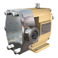
SPX TL4/0535 Instruction Manual (112 pages)
Rotary Lobe Pumps
Brand:
SPX
| Category:
Water Pump
| Size: 6.2 MB
Table of Contents
Table of Contents
3
1 Introduction
7
General
7
Receipt, Storage and Handling
7
Receipt, Storage
7
Handling
7
General Safety Instructions
8
General
8
Pump Units
10
Pump Unit Handling
10
Installation
10
Before Commissioning the Pump Unit
11
Disassembly/Assembly of the Coupling Guard
11
Name Plate - CE Declaration of Conformity
11
Pump Designation
12
Pump Model and Serial Number
14
Pump Standard Parts
14
General Performance
15
2 Function, Design, Installation
16
Operating Principle
16
Operating Parameters
16
System Design and Installation
17
Installations with CIP-Systems, Cleaning in Place
19
Installations with SIP-Systems, Sterilising in Place
19
Start
19
Shutdown
20
Routine Maintenance
20
Trouble Shooting Chart
21
Heating and Cooling Jackets
22
3 Technical Data
23
Rotor Clearances
23
Rotors in Duplex Steel
23
Lubricants
24
Material Specification
25
Machined Parts - Pump
25
Dimensional Drawings and Weights
26
Standard - Horizontal
26
Vertical Mounting - Thread Connection
27
Vertical Mounting - Flange Conncection
28
Flanges
29
Standard Pump
29
Enlarged Inlet
29
Thread and Clamp Connections
30
DIN and ANSI Flanges
32
Weights
33
Weights Standard Pump
33
Sound Level
34
4 Disassembly and Assembly Instructions
35
Tools to be Used
35
General Instructions
36
O-Rings and Lip Seals
36
Shutdown
36
Tightening Torque [Nm] for Nuts and Screws
37
Disassembly
38
Pump Cover and Rotor Removal
38
Disassembly of Seals
38
Single Mechanical Seal
39
Lip Seal
39
O-Ring Seal
39
Double Mechanical Seal
40
Rotor Case and Flushing Cover Disassembly
40
Gearbox Disassembly
41
Foot Disassembly
43
Assembly
43
Foot Assembly
43
Gearbox Assembly
44
Flushing Cover Assembly
47
Rotor Case Assembly
48
Seal Assembly
48
Single Mechanical Seal - General
48
Single Mechanical Seal
49
Lip Seal
49
O-Ring Seal
50
Double Mechanical Seal
50
Rotor and Pump Cover Assembly
51
5 Special Tools
53
General
53
Assembly Tool for Lip Seals
53
Assembly Tool for Lip Seal
54
Assembly Tool for Needle Bearings
54
Assembly Tool for Cover
55
Assembly Tool for Lip Seals
55
6 Sectional Drawings and Part List
56
Overview
56
Recommended Spare Parts
57
Recommended Spare Parts
58
Hydraulic Part
59
Hydraulic Part, Complete
59
Topkits Options
60
Kit for Flush Covers
60
Service Kit for Quench/Flush
61
O-Ring Kit for Hydraulic Part
62
O-Ring Kit for Hydraulic Part with Safety Relief Valve
63
Rotor Case Options
64
Pump Cover
64
Flat Pump Cover
64
Gearbox
65
Gearbox Complete
65
Part List - Gearbox
66
Feet Options
67
Service Kit for Gearbox
68
7 Single Mechanical Seal
69
General Information
69
Machined Parts - Seal Assembly Parts and Flush Covers
70
Seal Options
71
Single Mechanical Seal
71
Single Mechanical Seal with Quench/Flush
72
O-Ring Kit for Single Mechanical Seal With/Without Quench/Flush
73
8 Double Mechanical Seal
74
General
74
Machined Parts - Seal Assembly Parts and Flush Covers
75
Seal Options
76
Double Mechanical Seal M74-D60 - TL2/0074 and TL3/0234
76
Double Mechanical Seal M74-D60 - TL4/0535, TL4/2316 and TL4/3497
77
Tl3/0953
78
Double Mechanical Seal M74-D61 - TL2/0234, TL2/0301, TL3/0677 TL3/0953
78
O-Ring Kit for Double Mechanical Seal
79
9 Single and Double O-Ring Seal
80
General Information
80
Seal Options
81
Single O-Ring Seal
81
Double O-Ring Seal with Quench/Flush
82
O-Ring Kit
83
O-Ring Kit for Single O-Ring Seal
83
O-Ring Kit for Double O-Ring Seal
84
10 Hard Lip Seal
85
General
85
Seal Options
86
Hard Lip Seal -TL1, TL2, TL3
86
Hard Lip Seal - TL4
87
Hard Lip Seal with Quench/Flush - TL1, TL2, TL3
88
Hard Lip Seal with Quench/Flush - TL4
89
O-Ring Kit for Hard Lip Seal With/Without Quench/Flush
90
11 Quench and Flush Connections
91
Seal Plans
91
Pump Connections in Horizontal Position
91
Pump Connections in Vertical Position
93
12 Valves
95
Heating and Cooling Jackets
95
Built-On Safety Relief Valves
95
General Description
96
Safety Relief Valve - Spring Loaded
97
Spring Loaded
97
Spring Loaded Completely Opened
97
Safety Relief Valve - Spring Loaded - Air Lifted
98
Spring Loaded - Air Lifted
98
Spring Loaded - Air Lifted with CIP/SIP Valve Function
99
Setting and Operating - Spring Loaded and Spring Loaded - Air Lifted
99
Safety Relief Valve - Air Loaded - Air Lifted
101
Air Loaded
101
Air Loaded - Air Lifted with CIP/SIP Valve Function
101
Setting and Operating - Air Loaded - Air Lifted Safety Relief Valves
102
13 Disassembly/Assembly
104
Spring Loaded Valves
104
Disassembly
104
Assembly
104
Spring Loaded - Air Lifted Valves
105
Disassembly
105
Assembly
105
Air Loaded - Air Lifted Valves
106
Disassembly
106
Assembly
106
14 Dimensional Drawings and Weights
107
Safety Relief Valves with Heating/Cooling Jacket
107
Weights Safety Relief Valve
108
15 Sectional Drawings and Parts Lists
109
Pump Cover with Safety Relief Valve - Spring Loaded
109
Pump Cover with Safety Relief Valve - Spring Loaded - Air Lifted
110
Pump Cover with Safety Relief Valve - Air Loaded - Air Lifted - TL1
111
Tl2, Tl3
111
Pump Cover with Safety Relief Valve - Air Loaded - Air Lifted - TL4
112
Advertisement
Advertisement
Related Products
SPX TL4/2316
SPX TL4/3497
SPX Johnson Pump TopLobe TL4
SPX TL3/0953
SPX TL2/0074
SPX TL3/0677
SPX Johnson Pump TopLobe TL2
SPX Johnson Pump TopLobe TL3
SPX Johnson Pump TopLobe TL1
SPX TL1/0100
SPX Categories
Water Pump
Control Unit
Tools
Industrial Equipment
Security Sensors
More SPX Manuals
Login
Sign In
OR
Sign in with Facebook
Sign in with Google
Upload manual
Upload from disk
Upload from URL