Advertisement
Quick Links
LTE-IV, LTE-IA, and LTE-IC Communicators – Quick Installation Guide
For Online Support visit: https://mywebtech.honeywellhome.com/
General Information and Component Identification
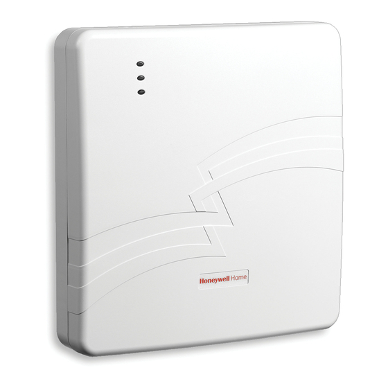
Congratulations on your purchase of Honeywell's LTE-IV/LTE-IA communicator (LTE-IC
in Canada). These communicators send alarms and messages from the security
system's control panel to AlarmNet for subsequent transfer to the central monitoring
station.
In addition to alarm reporting, they provide upload/downloading capability of Honeywell's
control panel programming data. Refer to the Installation and Setup Guide for the use of
these features.
These communicators represent the most innovative communication technology for the
security industry and use sophisticated encryption to ensure the highest level of security.
This guide addresses a simple installation using default programming values where
possible and is applicable for the majority of installations. For detailed information on
UL, ULC, and configuration of remote services, please refer to the appropriate
Installation and Setup Guide for the product. The LTE-IV, LTE-IA and LTE-IC are
henceforth referred to as the communicator or communications module.
The communicator requires an AlarmNet account. For new installations, please
obtain the account information from the central station prior to programming.
For control panels that do not support ECP, refer to the installation guide to use Zone
Trigger Mode.
The control panel treats the communicator as an ECP device, so ensure to program
the control panel with the communicator's device address. Refer to the control
panel's Installation and Setup Guide for details.
REMOTE SERVICES
Honeywell offers secure web based services that enable users to remotely monitor and
control their security system. These web services enable users to; monitor and control
their security system from a website or smartphone, receive email notifications of system
events, and receive event confirmations.
Dealers can enroll their customers for "Remote Services" by using the AlarmNet 360
website. Once enabled, the specific programming fields associated with these features
can be programmed into the communications device either remotely using the AlarmNet
360 website or locally using the 7720P programming tool.
1. Determine Signal Strength and Select a Location
The communicator must be mounted indoors. When choosing a suitable mounting location,
understand that signal strength is very important for proper operation. For most installations
using the internal antenna, mounting the unit as high as practical, and avoiding large metal
components provides adequate signal strength for proper operation.
In this step, you will use the communicator to determine signal strength in order to find a
suitable mounting location.
* LTE-I Initial Power Up: Upon initial power up, the communicator LEDs blink in repeated
sequence from top to bottom indicating network initialization.
Green (REG) Yellow (TX/RX) Red (FAULT)
This sequence may take up to 15 minutes. Do not reset power during this time.
When initialization is complete, the Signal Quality display LEDs will light and the yellow and
red LEDs may blink (per their respective functions).
After initial network setup, subsequent resets or power ups can take up to 90 seconds.
2. Mount and Wire the Communicator
1. Locate the case back over the selected mounting position such that the opening in the case
back is aligned with the wire/cable opening on the mounting surface.
2. Pass the wires/cable through the opening in the case back, or route through the removable
side knockouts located on the back cover. Then secure the case back to the mounting
surface using four screws (supplied). Make the following connections:
RED
+12V AUX
BLK
GND
YEL
DATA OUT
GRN
DATA IN
VISTA CONTROL PANEL
Distance from
Minimum
Control Panel
Wire Gauge
75 ft (23m)
#22
120 ft (37m)
#20
3. When all wiring has been completed (including the Internet cable if used), attach the case
front. Position the top first, then press the bottom section until it snaps in place. Secure
bottom using the supplied cover screw. (Required for UL installations.)
4. You may power up the communicator and control panel.
3. Connect the Internet Cable
Connect one end of the Ethernet cable (Category 5) to the communicator's RJ45 Ethernet
connector and the other end to the cable/DSL router as shown in the figure.
For UL installations, the Ethernet connection between the communicator and
the router cannot exceed 12 feet. Both units must be located within the
UL
same room.
Use a Listed cable/DSL router suited for the application.
TRANSFORMER
TB1
1
AC INPUT 1
AC INPUT 2
2
3
ECP (+) VOLTAGE INPUT
GND
4
5
ECP DATA IN
ECP DATA OUT
6
J1
COMMUNICATIONS
MODULE
Distance from
Minimum
Control Panel
Wire Gauge
170 ft (52m)
#18
270 ft (82m)
#16
Due to Honeywell's continuing effort to improve our products, your device may look slightly different than
pictured.
STATUS LED
MESSAGE LED
FAULT LED
7720P
PROGRAMMER
PORT
TB 1
AC 1
AC 2
12V DC IN
GND
ECP INPUT
ECP OUTPUT
MOUNTING HOLE
CONNECTOR
FOR USE WITH
DCID ONLY
J1
TAMPER
BATTERY
SWITCH
CONNECTOR
Note: Read and follow the RF Exposure notice on the other side.
1. Unpack the communicator and open the case by pushing in the two bottom tabs with a screwdriver
while separating the case front.
2. Temporarily connect the AC transformer or battery to the communicator.
3. Choose the installation site with the best signal strength by observing the signal quality bar
graph. Signal strength should be within 2-5 bars. The best signal strength is usually found at the
highest point in the building, near a window.
4. Mark the location for the communicator.
MOUNTING
SURFACE
BATTERY
OPTIONAL
KNOCKOUTS
BATTERY
CONNECTOR
INTERNAL
ANTENNA
1
2
3
4
5
6
BLACK
7
8
9
10
11
1
RJ45
NETWORK
ETHERNET
CONNECTIVITY
PORT
LEDs
(SUPERVISED)
CASE
BACK
TAB
WIRING
TAB
COVER SECURING SCREW
7720P
PROGRAM
CONNECTOR
J1
FACTORY
USE ONLY
CELLULAR
STATUS LED
INTERNAL
ANTENNA
SIGNAL QUALITY /
MODE AND
STATUS LEDs
RED
MOUNTING HOLE
(UNDER BATTERY)
BATTERY CLIP
BATTERY
SCREW
MODE SWITCH
MOUNTING
SCREW (4)
(TYP)
OPTIONAL WIRING
KNOCKOUT
CASE
FRONT
RJ45
(FOR INTERNET
CONNECTION)
TO ROUTER
Advertisement

Related Manuals for Honeywell LTE-IV


Summary of Contents for Honeywell LTE-IV
- Page 1 LTE-IV, LTE-IA, and LTE-IC Communicators – Quick Installation Guide For Online Support visit: https://mywebtech.honeywellhome.com/ General Information and Component Identification Due to Honeywell's continuing effort to improve our products, your device may look slightly different than Congratulations on your purchase of Honeywell's LTE-IV/LTE-IA communicator (LTE-IC pictured.
- Page 2 • If using an indoor antenna, have a quality outdoor antenna installed. Declaration of Conformity: Honeywell International, conformité du fournisseur : Honeywell International, 2 • Reorient the receiving antenna until interference is reduced or eliminated. • Move the radio or television receiver away from the receiver/control panel.
Need help?
Do you have a question about the LTE-IV and is the answer not in the manual?
Questions and answers