
Related Manuals for Honeywell KHF 1050


Summary of Contents for Honeywell KHF 1050
- Page 1 Preliminary - Subject to Change Without Notice SYSTEM INSTALLATION MANUAL KHF 1050 HF COMMUNICATION SYSTEM MANUAL NUMBER 006-10640-0000 REVISION 0, March 2003...
- Page 2 ©2003 Honeywell International Inc. REPRODUCTION OF THIS PUBLICATION OR ANY PORTION THEREOF BY ANY MEANS WITHOUT THE EXPRESS WRITTEN PERMISSION OF HONEYWELL IS PROHIBITED. FOR FURTHER INFORMATION CONTACT THE MANAGER, TECHNICAL PUBLICATIONS, HONEYWELL, ONE TECHNOLOGY CENTER, 23500 WEST 105TH STREET OLATHE KS...
-
Page 3: Revision 0 10640I00.Slk
Preliminary - Subject to Change Without Notice System Installation Manual P/N 006-10640-0000 KHF 1050 HF Communication System (Also known as Primus HF 1050) KAC 1052 Antenna Coupler KPA 1052 Power Amplifier KRX 1053 Receiver/Exciter Compatible HF Control Units Revision 0 23-10-09 10640I00.SLK... -
Page 4: Rh-1
Preliminary - Subject to Change Without Notice KHF 1050 SYSTEM INSTALLATION MANUAL REVISION HISTORY KHF 1050 SYSTEM INSTALLATION MANUAL 23-10-09 ----------------------------------------------------------------- PART NUMBER DATE DESCRIPTION 006-10640-0000 Mar/2003 Original issue. Revision 0 RH-1 23-10-09 10640I00.SLK Mar/2003... -
Page 5: Rr-1
Preliminary - Subject to Change Without Notice KHF 1050 SYSTEM INSTALLATION MANUAL REVISION HISTORY KHF 1050 SYSTEM INSTALLATION MANUAL 23-10-09 ----------------------------------------------------------------- PART NUMBER DATE DESCRIPTION Revision 0 RH-2 23-10-09 10640I00.SLK Mar/2003... -
Page 6: Revision 0 10640I00.Slk
Preliminary - Subject to Change Without Notice KHF 1050 SYSTEM INSTALLATION MANUAL RECORD OF REVISIONS REV. REVISION DATE REV. REVISION DATE DATE INSERTED DATE INSERTED Revision 0 RR-1 23-10-09 10640I00.SLK Mar/2003... -
Page 7: Revision 0 10640I00.Slk
Preliminary - Subject to Change Without Notice KHF 1050 SYSTEM INSTALLATION MANUAL RECORD OF REVISIONS REV. REVISION DATE REV. REVISION DATE DATE INSERTED DATE INSERTED Revision 0 RR-2 23-10-09 10640I00.SLK Mar/2003... -
Page 8: Table Of Contents
Preliminary - Subject to Change Without Notice KHF 1050 SYSTEM INSTALLATION MANUAL COMMENTARY: LEP TO BE UPDATED UPON COMPLETION OF MANUAL LIST OF EFFECTIVE PAGES SUBJECT PAGE DATE SUBJECT PAGE DATE Title Mar/2003 Installation and 2001 Mar/2003 Mar/2003 Maintenance 2002... -
Page 9: List Of Effective Pages
Preliminary - Subject to Change Without Notice KHF 1050 SYSTEM INSTALLATION MANUAL COMMENTARY: LEP TO BE UPDATED UPON COMPLETION OF MANUAL LIST OF EFFECTIVE PAGES SUBJECT PAGE DATE SUBJECT PAGE DATE F 2125 Mar/2003 2126 Blank F INDICATES FOLDOUT PAGES - PRINT ONE SIDE ONLY... -
Page 10: Tc-1
Preliminary - Subject to Change Without Notice KHF 1050 SYSTEM INSTALLATION MANUAL COMMENTARY: TOC TO BE UPDATED UPON COMPLETION OF MANUAL TABLE OF CONTENTS INTRODUCTION SECTION PAGE General INTRO-1 Layout of Material INTRO-1 Revision Service INTRO-1 DESCRIPTION AND OPERATION SECTION... -
Page 11: Table Of Contents
Preliminary - Subject to Change Without Notice KHF 1050 SYSTEM INSTALLATION MANUAL COMMENTARY: TOC TO BE UPDATED UPON COMPLETION OF MANUAL TABLE OF CONTENTS TESTING AND FAULT ISOLATION SECTION PAGE Fault Isolation 1001 System Performance Check 1002 A. Preliminary Check 1002 B. -
Page 12: Table Of Contents
Preliminary - Subject to Change Without Notice KHF 1050 SYSTEM INSTALLATION MANUAL COMMENTARY: TOC TO BE UPDATED UPON COMPLETION OF MANUAL TABLE OF CONTENTS Maintenance Procedures 2075 A. In-Aircraft Adjustments 2075 B. System Protection 2075 C. Lubrication 2076 D. Cleaning 2076 10. -
Page 13: Table Of Contents
Preliminary - Subject to Change Without Notice KHF 1050 SYSTEM INSTALLATION MANUAL COMMENTARY: TOC TO BE UPDATED UPON COMPLETION OF MANUAL TABLE OF CONTENTS Revision 0 TC-4 23-10-09 10640I00.SLK Mar/2003... -
Page 14: General
KHF 1050 SYSTEM INSTALLATION MANUAL INTRODUCTION General This manual provides description and operation, testing, fault isolation, installation, maintenance, and flightline checkout procedures for the KHF 1050 HF Communication System. Layout of Manual Section 1 Description and Operation Section 1000 Testing and Fault Isolation... - Page 15 Preliminary - Subject to Change Without Notice KHF 1050 SYSTEM INSTALLATION MANUAL Blank Page Revision 0 INTRO-2 23-10-09 10640I00.SLK Mar/2003...
-
Page 16: Glossary
Preliminary - Subject to Change Without Notice KHF 1050 SYSTEM INSTALLATION MANUAL Glossary of Terms and Abbreviations Aircraft Automatic Gain Control Amplitude Modulation Equivalent The ready to operate status of a function/device. Clarifier Clock COMP Compatible CPLR Coupler Ground High Frequency... -
Page 17: Glossary
Preliminary - Subject to Change Without Notice KHF 1050 SYSTEM INSTALLATION MANUAL Glossary of Terms and Abbreviations Radio Management Unit RTCA Radio Technical Commission for Aeronautics Return Receive SELCAL SELective CALling SELECTIVITY The ability of a receiver to differentiate desired... -
Page 18: Description And Operation
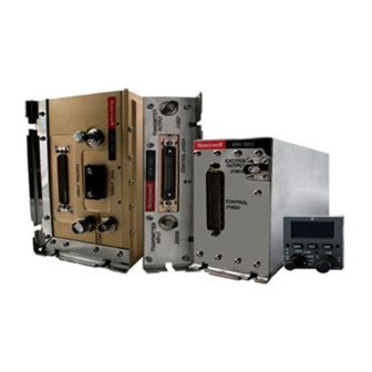
KHF 1050 SYSTEM INSTALLATION MANUAL DESCRIPTION AND OPERATION 1. System Description A basic KHF 1050 HF Communication System consists of three individual units: KAC 1052 Antenna Coupler, KPA 1052 Power Amplifier, and KRX 1053 Receiver/Exciter. A compatible control unit is also required. Control units compatible with the system include the Gables PS440, Honeywell MCDU Multifunction Control and Display Unit and Honeywell RM-855 Radio Management Unit. -
Page 19: Revision 0 10640I00.Slk
Preliminary - Subject to Change Without Notice KHF 1050 SYSTEM INSTALLATION MANUAL PS440 Control Display Unit Figure 2 MCDU Multfunction Control and Display Unit Figure 3 Revision 0 Page 2 23-10-09 10640I00.SLK Mar/2003... -
Page 20: System Overview
RM-855 Radio Management Unit Figure 4 1.A. System Overview The KHF 1050 HF voice and data communication system is a solid state design with 200 watts (PEP) of output power, operating at 28 Vdc. Frequency of operaton ranges between 2.0 and 29.9999 MHz with 100 Hz resolution. -
Page 21: Operation
KAC 1052 Antenna Coupler to the KRX 1053 Receiver/Exciter. The KHF 1050 can be installed as a single or dual HF system. In a dual system when one system is transmitting, receive on the other system is disbled. The single antenna in a dual system can be tuned to only one frequency at any given time. -
Page 22: Operation
HF2. IT IS RECOMMENDED THAT HF1 CABLES BE COLOR CODED RED AND HF2 CABLES BE COLOR CODED GREEN. Several operating mode options are available for the KHF 1050 HF system to meet particular operational needs. USB (upper sideband A3J) AME (amplitude modulation equivalent A3H) are standard modes of operation permitted on all system configurations. - Page 23 Preliminary - Subject to Change Without Notice KHF 1050 SYSTEM INSTALLATION MANUAL Typical System Block Diagram Figure 5 Revision 0 Page 6 23-10-09 10640I00.SLK Mar/2003...
-
Page 24: System Component Descriptions
This version of the block diagram corresponds to the content of Technical Specification Rev C, January, 2002. 1.B. System Component Descriptions The required and optional equipment of a KHF 1050 HF Communication System is listed below: • KAC 1052 Antenna Coupler (required) •... -
Page 25: Component Installation Kits
(P/N 7025725-901, -910, -920, -930, -940) This multi-function radio controller provides control of all the functions of the KHF 1050 system via ARINC 429. Frequency, channel, squelch type and level, emission type and power level are selected from the MCDU. -
Page 26: Revision 0 10640I00.Slk
Preliminary - Subject to Change Without Notice KHF 1050 SYSTEM INSTALLATION MANUAL Part Number Description UM Qty 057-05944-0034 VERT TSO KIT LABEL, KAC 1052 071-00200-0000 VERT TRAY ASSEMBLY, KAC 1052 KAC 1052 Single Vertical Installation Kit (tray only) (P/N:050-03658-0001) Table 2... -
Page 27: Revision 0 10640I00.Slk
Preliminary - Subject to Change Without Notice KHF 1050 SYSTEM INSTALLATION MANUAL Part Number Description UM Qty 030-00005-0000 CONN BNC UG 88C/U 030-01157-0011 SOCKET CRMP 20G 030-03517-0004 CONN, D-SUB, RECPT, CRMP, HOOD, 37 POS 047-06261-0036 GROUND STRAP 057-05944-0030 DUAL VERT KAC 1052 TSO KIT LABEL... -
Page 28: Revision 0 10640I00.Slk
Preliminary - Subject to Change Without Notice KHF 1050 SYSTEM INSTALLATION MANUAL 1.C.(2) KPA 1052 Power Amplifier Installation Kits Part Number Description UM Qty 030-00005-0000 CONN BNC UG 88C/U 030-01157-0011 SOCKET CRMP 20G 030-01466-0002 CONN, D-SUB, CONTACT, CRMP, PWR, SIZE 8... -
Page 29: Revision 0 10640I00.Slk
Preliminary - Subject to Change Without Notice KHF 1050 SYSTEM INSTALLATION MANUAL 1.C.(3) KRX 1053 Receiver/Exciter Installation Kits Part Number Description UM Qty 030-00005-0000 CONN BNC UG 88C/U 030-01451-0000 CONTACT SOCKET EA 104 030-03518-0001 CONN, D-SUB, RECPT, HI-DENS, W/HOOD, 104 POS... -
Page 30: Operation
Preliminary - Subject to Change Without Notice KHF 1050 SYSTEM INSTALLATION MANUAL Part Number Description UM Qty 3280 VERTICAL FIN ANCHOR KIT 5 ARM 200-6LV VERTICAL FIN “V” TENSION KIT 50 ARM 300-205 ANTI-PRECIPITATION ANTENNA WIRE 25 ARM 300-20E 30°... -
Page 31: Revision 0 10640I00.Slk
Preliminary - Subject to Change Without Notice KHF 1050 SYSTEM INSTALLATION MANUAL Equipment Required But Not Supplied AIRCRAFT EQUIPMENT DESCRIPTION Grounded Tranline Grounded tranline: Towel bar with 1 inch diameter recommended. Contact: Trivec-Avant Corp. 17831 Jamestown Ln. Huntington Beach, CA 92647... -
Page 32: Revision 0 10640I00.Slk
Preliminary - Subject to Change Without Notice KHF 1050 SYSTEM INSTALLATION MANUAL Equipment Required But Not Supplied AIRCRAFT EQUIPMENT DESCRIPTION AN-18 1,909 Nominal Circular Mil Area* 0.115 inches Max. Overall Diameter 6.44 ohms Max. per 1000 feet @ 20°C 16 amps Max. Cont. Current Rating** 10 amps Max. -
Page 33: Related Publications
Table 15 WARNING: THE HIGH VOLTAGE HN CABLES ARE SPECIFICALLY DESIGNED TO WITHSTAND THE HIGH VOLTAGE GENERATED BY THE KHF 1050 SYSTEM. THEY CAN NOT BE REPLACED BY CABLES THAT HAVE NOT BEEN TESTED TO THESE HIGH VOLTAGES AT ALTITUDE. THESE... -
Page 34: Component Configurations
Field Office. 2. Component Configurations System component configurations are listed in this section. The overall configuration of a KHF 1050 HF system is dependent on the component versions installed in the aircraft. 2.A. KAC 1052 Antenna Coupler Unit Configurations PART NUMBER... -
Page 35: Radio Management Unit Configurations
Preliminary - Subject to Change Without Notice KHF 1050 SYSTEM INSTALLATION MANUAL 2.D. PS440 Control Display Unit Configurations PART NUMBER VERSION BEZEL LCD BACKLIGHTING 071-01605 -0101 Gray White 071-01605 -0201 Black White 071-01605 -1101 Gray Amber 071-01605 -1201 Black Amber... -
Page 36: General Specifications
3. System Leading Particulars 3.A. General Specifications The KHF 1050 HF System is a solid state design with 200 watts PEP of output power, supplied by 28 VDC, with an operational frequency range of 2.0 to 29.9999 MHz with 100kHz resolution. -
Page 37: Operation
Modes of Operation Table 23 3.B.(2) 23 MHz Limit Mode The KHF 1050 HF system can be strapped to limit the frequency of operation to an upper limit of 22.9999 MHz for certification in countries that may require such an upper frequency limit. -
Page 38: Revision 0 10640I00.Slk
Preliminary - Subject to Change Without Notice KHF 1050 SYSTEM INSTALLATION MANUAL 3.B.(5) Data Mode When the KRX 1053 Receiver/Exciter is operating in the DATA mode, interface with data modems or secure voice systems is enabled. The external modem inputs and external modem outputs are available to bypass squelch and compression functions in the KRX 1053. -
Page 39: Component Leading Particulars
Preliminary - Subject to Change Without Notice KHF 1050 SYSTEM INSTALLATION MANUAL 3.C. Component Leading Particulars Leading particulars for components of the KHF 1050 HF system are listed below. 3.C.(1) KAC 1052 Antenna Coupler, Leading Particulars CHARACTERISTIC DESCRIPTION Weight: Refer to Figure 2028 (P/N 155-01774-2028) -
Page 40: Revision 0 10640I00.Slk
Preliminary - Subject to Change Without Notice KHF 1050 SYSTEM INSTALLATION MANUAL 3.C.(4) PS440 Control Display Unit, Leading Particulars NOTE: Refer to the PS440 Control Display Unit Component Maintenance Manual P/N 006-15655-XXXX for more description of the PS440. CHARACTERISTIC DESCRIPTION... -
Page 41: System Function
KPA 1052 Power Amplifier KRX 1053 Receiver/Exciter Compatible Control Display Unit The basic KHF 1050 HF system is a mobile communication system for aircraft. It operates in a frequency range between 2.0 and 29.9999 MHz offering several different emission modes to provide voice communication. -
Page 42: Dual System
Preliminary - Subject to Change Without Notice KHF 1050 SYSTEM INSTALLATION MANUAL 4.A.(2) Channel Operation COMMENTARY: INSERT CHANNEL OPERATION DESCRIPTION HERE. 4.A.(3) Direct Frequency Mode COMMENTARY: INSERT DIRECT FREQUENCY MODE OPERATION HERE. 4.B. Dual System COMMENTARY: INSERT ANY DUAL SYSTEM FUNCTIONALITY INFO HERE. -
Page 43: Testing And Fault Isolation
Intermittent or improperly connected cables or connectors. Defective units. Poorly regulated aircraft DC power. Poor grounding of KHF 1050 HF system or poor aircraft bonding. Audio ground loops. RF interference. CAUTION: POWER CARTS MAY REGULATE POORLY WHEN SUBJECTED TO STRONG RF FIELDS. -
Page 44: Preliminary Check
Preliminary - Subject to Change Without Notice KHF 1050 SYSTEM INSTALLATION MANUAL 2.A. Preliminary Check 1. Prior to turning the system on, ensure that all connectors are properly seated in their proper location. 2. Turn the system on. As the system turns on it performs a brief self-test. -
Page 45: Operation
Preliminary - Subject to Change Without Notice KHF 1050 SYSTEM INSTALLATION MANUAL FUNCTION TURN ON PILOT CONT Label 351 Discrete Line Check Flash ROM Checksum DSP ROM DSP RAM DSP CLOCK (60MHz) RF Board XMT Operation RF Board RCV Operation... -
Page 46: Operation
Preliminary - Subject to Change Without Notice KHF 1050 SYSTEM INSTALLATION MANUAL 5. KPA 1052 Power Amplifier Built-In-Test The power amplifier design incorporates provisions for monitoring its own operation to detect any condition or occurrence that the operator (a flight crew member) might observe and interpret as a reason for requesting a maintenance action. -
Page 47: Operation
Preliminary - Subject to Change Without Notice KHF 1050 SYSTEM INSTALLATION MANUAL 6. KAC 1052 Antenna Coupler Built-In-Test The antenna coupler design incorporates provisions for monitoring its own operation to detect any condition or occurrence that the operator (a flight crew member) might observe and interpret as a reason for requesting a maintenance action. -
Page 48: Receiver Performance Check
Preliminary - Subject to Change Without Notice KHF 1050 SYSTEM INSTALLATION MANUAL Impedance sensors Note 1: The Label 351 information is actually sent by the KRX 1053 in response to RS-422 serial data sent by the KAC 1052 to the KRX 1053. -
Page 49: Transmitter Performance Check
These stations transmit in the AM mode. However, they can be received by the KHF 1050 System in the USB Voice (UV), LSB Voice (LV), AM or Reduce-Carrier (RC) modes. -
Page 50: Revision 0 10640I00.Slk
Preliminary - Subject to Change Without Notice KHF 1050 SYSTEM INSTALLATION MANUAL In the event that the operating frequency selected had previously been tuned by the KAC 1052 Antenna Coupler, the antenna coupler will utilize stored tune information and match to the antenna in less than 50msec. However, changes in antenna impedance can occasionally result in the KAC 1052 needing to retune on a previously tuned frequency. -
Page 51: Fault Isolation
If unit fails to retune, select a different frequency and try to retune the antenna at the new frequency. Turn the KHF 1050 system off and check the coaxial cable connections between the KAC 1052 and the antenna feedpoint. Ensure that there is no evidence of... -
Page 52: Installation And Maintenance
If any component is damaged, notify the transportation carrier immediately. 3. Pre-installation Testing All components of the KHF 1050 HF system have been adjusted and tested before shipment and pre-installation testing is not required. If pre-installation bench testing of any unit is desired, refer to bench test section of the applicable maintenance manual. -
Page 53: Equipment Changes And Markings
The KHF 1050 HF system should be installed in the aircraft in a manner consistent with acceptable workmanship and engineering practices and according to instructions set forth in this publication. -
Page 54: Revision 0 10640I00.Slk
Preliminary - Subject to Change Without Notice KHF 1050 SYSTEM INSTALLATION MANUAL NOTE: Due to the high level of RF voltage the KHF 1050 system is capable of generating, only a specially fabricated Honeywell feedline may be used. Refer to Section 1.C.(1) for appropriate part numbers. -
Page 55: Operation
RM-855 mounting instructions. 5.B.(5) Antenna Location The antenna is a primary factor for maximum performance of the KHF 1050 HF system. While numerous options are available in the choice of antenna configurations, some configurations are better suited for a particular installation than others. -
Page 56: Revision 0 10640I00.Slk
Preliminary - Subject to Change Without Notice KHF 1050 SYSTEM INSTALLATION MANUAL "V" and long wire antenna performance will be enhanced by striving to meet the following criteria: Maximize the length of wire (up to approximately 60 feet or 18 m.). The total length of the antenna should be at least 25 feet (7.6 m). -
Page 57: Revision 0 10640I00.Slk
Preliminary - Subject to Change Without Notice KHF 1050 SYSTEM INSTALLATION MANUAL 5.B.(6)(a)2 Inverted “V” Antenna Mounting Location The inverted “V” antenna is recommended when a wing “V” is not practical and the antenna coupler is to be mounted in the aft position of the aircraft. The inverted “V”... -
Page 58: Operation
Preliminary - Subject to Change Without Notice KHF 1050 SYSTEM INSTALLATION MANUAL Typical Long Wire Antenna Figure 2003 5.B.(6)(c) Short Grounded Wire Antenna Mounting Location Short grounded wire antennas may be utilized on higher speed and/or high altitude aircraft. These short wire... -
Page 59: Revision 0 10640I00.Slk
Preliminary - Subject to Change Without Notice KHF 1050 SYSTEM INSTALLATION MANUAL Typical Short Wire to Vertical Stabilizer Antenna Figure 2004 5.B.(6)(c)2 Short Wire to Wing or Horizontal Stabilizer Antenna Mounting Location In installations where the short wire to the vertical... -
Page 60: Revision 0 10640I00.Slk
Preliminary - Subject to Change Without Notice KHF 1050 SYSTEM INSTALLATION MANUAL Typical Short Wire to Horizontal Stabilizer Antenna Figure 2006 5.B.(6)(d) Shunt Antenna Mounting Location Two types of shunt antennas are commonly used. The most preferable type, on a fixed wing aircraft, is designed by the airframe manufacturer as a part of the airframe structure. -
Page 61: Revision 0 10640I00.Slk
Preliminary - Subject to Change Without Notice KHF 1050 SYSTEM INSTALLATION MANUAL A large diameter feedline exhibiting extremely low RF resistance must be used between the KAC 1052 Antenna Coupler and the antenna. Typical Shunt Leading Edge Antenna Figure 2007 5.B.(6)(d)2 Shorted Tranline or Towel Bar Antenna Mounting Location... -
Page 62: Interwiring And Cable Fabrication
Figure 2008 5.C. Interwiring and Cable Fabrication 5.C.(1) Fabrication and Routing Figure 2033 provides a KHF 1050 HF Communication System interconnect summary. Cabling must be fabricated according to the interwiring diagrams. The length of the wires to parallel pins should be approximately the same length, for best current distribution. -
Page 63: Operation
5.C.(3) Primary Power and Circuit Breaker Requirements All units in the KHF 1050 system should be protected by circuit breakers in the positive primary power lines. The KPA 1052 should use an individually dedicated 30 amp slow-acting circuit breaker. -
Page 64: Description And
Honeywell. Due to the high level of RF voltage the KHF 1050 system is capable of generating, substitute cables must not be used. Refer to Section 1.C.(1) for appropriate part numbers for the Honeywell supplied HN-to-HN feedline assemblies. -
Page 65: Revision 0 10640I00.Slk
Preliminary - Subject to Change Without Notice KHF 1050 SYSTEM INSTALLATION MANUAL KAC 1052 CONNECTOR PIN DEFINITIONS SIGNAL NAME DESCRIPTION TUN FAIL + TUNE FAIL + RC COM PHOTO-COUPLER COMMON SOURCE EXCTR TUN REQ - EXCTR TUNE REQUEST - FRAME GROUND... -
Page 66: Revision 0 10640I00.Slk
Preliminary - Subject to Change Without Notice KHF 1050 SYSTEM INSTALLATION MANUAL KAC 1052 CONNECTOR PIN DEFINITIONS SIGNAL NAME DESCRIPTION APC L APC LOW KAC 1052 Antenna Coupler Connector (J10521) Pin Definitions Table 2001 5.C.(5)(b) KPA 1052 Power Amplifier Connector... -
Page 67: Revision 0 10640I00.Slk
Preliminary - Subject to Change Without Notice KHF 1050 SYSTEM INSTALLATION MANUAL KPA 1052 CONNECTOR PIN DEFINITIONS SIGNAL NAME DESCRIPTION PA ALM + #2 PA ALARM + #2 PC COM PHOTO-COUPLER COMMON SOURCE PA BFRD KEY - PA BUFFERED KEY -... -
Page 68: Revision 0 10640I00.Slk
Preliminary - Subject to Change Without Notice KHF 1050 SYSTEM INSTALLATION MANUAL KRX 1053 CONNECTOR PIN DEFINITIONS SIGNAL NAME DESCRIPTION HF CONT INP #1(A) HF CONTROLLER INPUT #1(A) SPARE CPLR RXD BUS - BUFFERED KEY BUFFERED KEY - KEY EVENT... -
Page 69: Revision 0 10640I00.Slk
Preliminary - Subject to Change Without Notice KHF 1050 SYSTEM INSTALLATION MANUAL KRX 1053 CONNECTOR PIN DEFINITIONS SIGNAL NAME DESCRIPTION RC COM PHOTO-COUPLER COMMON SOURCE STUCK MIC PTCT STUCK MIC PROTECTION OTHER SIDE PTT OTHER SIDE PTT EXT DATA KEYLINE H... -
Page 70: Revision 0 10640I00.Slk
Preliminary - Subject to Change Without Notice KHF 1050 SYSTEM INSTALLATION MANUAL KRX 1053 CONNECTOR PIN DEFINITIONS SIGNAL NAME DESCRIPTION SELCAL AUD L SELCAL AUDIO LOW EXT MODEM AUD INP L EXT MODEM AUDIO INPUT LOW MIC AUD L MIC AUDIO LOW... -
Page 71: Revision 0 10640I00.Slk
Preliminary - Subject to Change Without Notice KHF 1050 SYSTEM INSTALLATION MANUAL KRX 1053 CONNECTOR PIN DEFINITIONS SIGNAL NAME DESCRIPTION DATA BUS SHLD GND GND DATA BUS SHIELD GROUND DATA BUS SHLD GND GND DATA BUS SHIELD GROUND DATA BUS SHLD GND... -
Page 72: Revision 0 10640I00.Slk
Preliminary - Subject to Change Without Notice KHF 1050 SYSTEM INSTALLATION MANUAL 5.C.(5)(d) PS440 Control Display Unit Connector PS440 Control Display Unit Connector (J1) Pin Configuration Figure 2012 PS440 CONNECTOR PIN DEFINITIONS FUNCTION 28 VDC In DC Ground Chassis Ground... -
Page 73: Revision 0 10640I00.Slk
Preliminary - Subject to Change Without Notice KHF 1050 SYSTEM INSTALLATION MANUAL PS440 CONNECTOR PIN DEFINITIONS FUNCTION Spare HF On/Off Out Spare ARINC 429 Out A Spare Reserved 28 VDC Dimming Bus ARINC 429 In #1A Test Out Reserved Spare... -
Page 74: Revision 0 10640I00.Slk
Preliminary - Subject to Change Without Notice KHF 1050 SYSTEM INSTALLATION MANUAL PS440 CONNECTOR PIN DEFINITIONS FUNCTION ARINC 429 In #1B Spare Spare Spare Spare Spare HFDL Inhibit In SDI Config In Reduced Carrier Inhibit In 0.1 kHz Enable In... -
Page 75: Revision 0 10640I00.Slk
Preliminary - Subject to Change Without Notice KHF 1050 SYSTEM INSTALLATION MANUAL 5.C.(5)(f) RM-855 Radio Management Unit Connector RM-855 Radio Management Unit Connector (J????) Pin Configuration Figure 2016 RM-855 CONNECTOR PIN DEFINITIONS FUNCTION CONNECT TO LRU IDENT OPEN - PILOT SIDE HF (ARINC SDI = 01B) -
Page 76: Revision 0 10640I00.Slk
Preliminary - Subject to Change Without Notice KHF 1050 SYSTEM INSTALLATION MANUAL RM-855 CONNECTOR PIN DEFINITIONS FUNCTION CONNECT TO C SELECT LEAVE OPEN BURST ENABLE JUMPER TO e - ARINC 429 BURST ENABLE STOP SCAN JUMPER TO u - STOP SCAN ENABLE... - Page 77 Preliminary - Subject to Change Without Notice KHF 1050 SYSTEM INSTALLATION MANUAL 5.C.(5)(f) BNC Connector Assembly (P/N 030-00005-0001) BNC Connector Assembly Procedure Figure 2017 Revision 0 Page 2026 23-10-09 10640I00.SLK Mar/2003...
-
Page 78: Revision 0 10640I00.Slk
Preliminary - Subject to Change Without Notice KHF 1050 SYSTEM INSTALLATION MANUAL 5.C.(6) Connector Pin Tools The crimping tool and associated positioner used during the fabrication of cables are identified in figure 2018. The insertion and extraction tools used during the fabrication of cables are identified in figure 2019. - Page 79 Preliminary - Subject to Change Without Notice KHF 1050 SYSTEM INSTALLATION MANUAL Insertion and Extraction Tools Figure 2019 Revision 0 Page 2028 23-10-09 10640I00.SLK Mar/2003...
-
Page 80: Strapping Options
Preliminary - Subject to Change Without Notice KHF 1050 SYSTEM INSTALLATION MANUAL 5.D. Strapping Options 5.D.(1) KRX 1053 Receiver/Exciter Strapping Options Refer to Table 2008 for KRX 1053 strapping options. 5.D.(1)(a) Power ON/OFF Control - (J10531-23) PWR CONT An external controller turns on the KRX 1053 Receiver/Exciter by asserting the POWER ON/OFF CONTROL discrete input. -
Page 81: Operation
Preliminary - Subject to Change Without Notice KHF 1050 SYSTEM INSTALLATION MANUAL In a system consisting of two external HF controllers, with one controller connected to HF CONTROLLER INPUT #1 data bus and the other connected to HF CONTROLLER INPUT... -
Page 82: Operation
Preliminary - Subject to Change Without Notice KHF 1050 SYSTEM INSTALLATION MANUAL Additionally, the KRX 1053 Receiver/Exciter sets the SDI field of all ARINC 429 transmitted messages to 10B (bit 9 = 0, bit 10 = 1). This condition identifies the system as HF #2. -
Page 83: Operation
Preliminary - Subject to Change Without Notice KHF 1050 SYSTEM INSTALLATION MANUAL The KRX 1053 Receiver/Exciter processor samples the state of this discrete input only at initial power application. The state of this discrete is assumed not to change during operation. -
Page 84: Revision 0 10640I00.Slk
Preliminary - Subject to Change Without Notice KHF 1050 SYSTEM INSTALLATION MANUAL The KRX 1053 Receiver/Exciter interprets a resistance of ten ohms or less between the EXTERNAL DATA KEYLINE HI and LO pins as a command to transmit, whether the LO pin is grounded or left floating. -
Page 85: Revision 0 10640I00.Slk
(or tune the antenna) on the left-side system. Unit/Pin Function Strapping Comment 76J1-23 Power MAU/MCDU May be grounded for KHF 1050 System On/Off to be be always on. 76J1-15 Tuning Mode Ground Accepts burst ARINC 429 input. 76J1-36 Stuck MIC Ground to limit transmission to 30 second default. -
Page 86: Operation
KHF 1050 SYSTEM INSTALLATION MANUAL Unit/Pin Function Strapping Comment 76J1-79 Right Side Side Ground if right-side system. Open Depenent if a single KHF 1050 installation. 76J1-98 Left Side Side Ground if left-side system. Open if Dependent a single KHF 1050 installation. 76J1-100 Narrow/Wide Open Allows 2.0000 to 29.9999 MHz... -
Page 87: Equipment Installation
Strap thickness should be 0.010 inches or greater. A one inch wide silver plated copper strap, available from Honeywell, is recommended. P/N 047-06261-0036 is a 36 inch length of the strap. 6.A.(3) Bonding Connection and Corrosion Prevention Techniques... -
Page 88: Revision 0 10640I00.Slk
Preliminary - Subject to Change Without Notice KHF 1050 SYSTEM INSTALLATION MANUAL NOTE: All nonconductive finishes such as paint, anodizing films, or zinc chromate, must be totally removed from the entire mating surface before assembly. Techniques such as spot-facing or cleaning only small area of the mating surfaces do not provide adequate RF bonding. -
Page 89: Revision 0 10640I00.Slk
Preliminary - Subject to Change Without Notice KHF 1050 SYSTEM INSTALLATION MANUAL Good RF bonding of the KAC 1052 Antenna Coupler to the aircraft fuselage is basic in achieving maximum efficiency from the system and eliminating any possible intereference to other systems in the aircraft. See Section 6.A for bonding considerations. -
Page 90: Revision 0 10640I00.Slk
Preliminary - Subject to Change Without Notice KHF 1050 SYSTEM INSTALLATION MANUAL power supply with a circuit breaker with not less than 25 Amp rating. 6.C.(3) Grounding Requirements Except for the ground provided by the feedline coax shield, bonding should not be done with braided wire but with solid conductive straps, typically one inch wide. -
Page 91: Antenna Installation
Preliminary - Subject to Change Without Notice KHF 1050 SYSTEM INSTALLATION MANUAL 6.D.(3) With the shock mounts removed and the tray laying flat against the mounting structure, center tap four positions at which the shock mounts will mount to the tray. -
Page 92: Inspection, System Checkout, And Flight Test Procedures
Visual Inspection Procedure Table 2010 7.B. System Checkout 7.B.(1) General The KHF 1050 HF Communication System requires three stages of post-installation testing to ensure proper operation: (1) A system interwiring check is performed before installation of system components and before power is applied, to verify that all aircraft and HF system interconnections are correct. -
Page 93: Flight Test
Preliminary - Subject to Change Without Notice KHF 1050 SYSTEM INSTALLATION MANUAL 7.B.(2) System Interwiring Check 7.B.(2)(a) Check that all cables and interwiring are installed according to the interwiring and cable fabrication instructions (section 5.C). 7.B.(2)(b) Check that all functions are properly strapped to reflect the aircraft system configuration (section 5.D). -
Page 94: Revision 0 10640I00.Slk
Preliminary - Subject to Change Without Notice KHF 1050 SYSTEM INSTALLATION MANUAL Frequency Band Daytime Distance Nighttime Distance (MHz) (miles) (miles) 10.0 300 to 1000 500 to 1800 or greater* 11.1 400 to 1200 600 to 1800 or greater* 13.3... -
Page 95: Revision 0 10640I00.Slk
Preliminary - Subject to Change Without Notice KHF 1050 SYSTEM INSTALLATION MANUAL 8.A.(2)(c) Reconnect appropriate cables to connector J10521. 8.B. KPA 1052 Power Amplifier Removal and Re-installation 8.B.(1) KPA 1052 Power Amplifier Removal 8.B.(1)(a) Detach cables from connector J10524. 8.B.(1)(b) Remove nut and washer on the GND post. Detach ground strap. -
Page 96: Revision 0 10640I00.Slk
Replace and secure the dust cover once the adjustment is complete. 9.B. System Protection The KHF 1050 system is primarily protected by circuit breakers located at the circuit breaker panel in the aircraft. The KPA 1052 contains an internal fuse for additional protection. -
Page 97: Operation
KHF 1050 SYSTEM INSTALLATION MANUAL 9.C. Lubrication No lubrication is required. There are no moving parts that require lubrication in the KHF 1050 HF Communication System. 9.D. Cleaning The exterior of the units should be wiped with lint-free cloth dampened with the approved cleaning agent, when deemed necessary, depending upon environmental exposure and intensity of use. - Page 98 Preliminary - Subject to Change Without Notice KHF 1050 SYSTEM INSTALLATION MANUAL KRX 1050 Adjustments Figure 2020 Revision 0 Page 2047 23-10-09 10640I00.SLK Mar/2003...
- Page 99 Preliminary - Subject to Change Without Notice KHF 1050 SYSTEM INSTALLATION MANUAL Blank Page Revision 0 Page 2048 23-10-09 10640I00.SLK Mar/2003...
- Page 100 Preliminary - Subject to Change Without Notice KHF 1050 SYSTEM INSTALLATION MANUAL COMMENTARY: INSERT OUTLINE DRAWING HERE WHEN AVAILABLE PS440 Control Display Unit Outline and Mounting (Dwg P/N ????) Figure 2022 Revision 0 Page 2049/2050 23-20-03 10640I00.SLK Mar/2003...
- Page 101 Preliminary - Subject to Change Without Notice KHF 1050 SYSTEM INSTALLATION MANUAL MCDU Multifunction Control and Display Unit Outline and Mounting (Dwg P/N 7025726-930 - Sheet 1 of 3) Figure 2023 Revision 0 Page 2051/2052 23-10-09 10640I00.SLK Mar/2003...
- Page 102 Preliminary - Subject to Change Without Notice KHF 1050 SYSTEM INSTALLATION MANUAL MCDU Multfunction Control Display Unit Outline and Mounting (Dwg P/N 7025726-930 - Sheet 2 of 3) Figure 2024 Revision 0 Page 2053/2054 23-20-03 10640I00.SLK Mar/2003...
- Page 103 Preliminary - Subject to Change Without Notice KHF 1050 SYSTEM INSTALLATION MANUAL MCDU Multifunction Control and Display Unit Outline and Mounting (Dwg P/N 7025726-930 - Sheet 3 of 3) Figure 2025 Revision 0 Page 2055/2056 23-10-09 10640I00.SLK Mar/2003...
- Page 104 Preliminary - Subject to Change Without Notice KHF 1050 SYSTEM INSTALLATION MANUAL RM-855 Radio Management Unit Outline and Mounting (Dwg P/N 7013270 sheet 1 of 2) Figure 2026 Revision 0 Page 2057/2058 23-20-03 10640I00.SLK Mar/2003...
- Page 105 Preliminary - Subject to Change Without Notice KHF 1050 SYSTEM INSTALLATION MANUAL RM-855 Radio Management Unit Outline and Mounting (Dwg P/N 7013270 sheet 2 of 2) Figure 2927 Revision 0 Page 2059/2060 23-20-03 10640I00.SLK Mar/2003...
- Page 106 Preliminary - Subject to Change Without Notice KHF 1050 SYSTEM INSTALLATION MANUAL KAC 1052 Antenna Coupler Single Horizontal Outline and Mounting (Dwg P/N 155-01774-0000) Figure 2028 Revision 0 Page 2061/2062 23-20-03 10640I00.SLK Mar/2003...
- Page 107 Preliminary - Subject to Change Without Notice KHF 1050 SYSTEM INSTALLATION MANUAL KAC 1052 Antenna Coupler Single Vertical Outline and Mounting (Dwg P/N 155-01772-0000) Figure 2029 Revision 0 Page 2063/2064 23-20-03 10640I00.SLK Mar/2003...
- Page 108 Preliminary - Subject to Change Without Notice KHF 1050 SYSTEM INSTALLATION MANUAL KAC 1052 Antenna Coupler Dual Vertical Outline and Mounting (Dwg P/N 155-01775-0000) Figure 2030 Revision 0 Page 2065/2066 23-20-03 10640I00.SLK Mar/2003...
- Page 109 Preliminary - Subject to Change Without Notice KHF 1050 SYSTEM INSTALLATION MANUAL KPA 1052 Power Amplifier Outline and Mounting (Dwg P/N 155-01750-0000) Figure 2031 Revision 0 Page 2067/2068 23-20-03 10640I00.SLK Mar/2003...
- Page 110 Preliminary - Subject to Change Without Notice KHF 1050 SYSTEM INSTALLATION MANUAL KRX 1053 Receiver/Exciter Outline and Mounting (Dwg P/N 155-01751-0000) Figure 2032 Revision 0 Page 2069/2070 23-20-03 10640I00.SLK Mar/2003...
- Page 111 Preliminary - Subject to Change Without Notice KHF 1050 SYSTEM INSTALLATION MANUAL COMMENTARY: INSERT INTERCONNECT DRAWING HERE WHEN AVAILABLE KHF 1050 HF System Interconnect (Dwg P/N 155-01762-0000) Figure 2033 Revision 0 Page 2071/2072 23-20-03 10640I00.SLK Mar/2003...
- Page 112 Preliminary - Subject to Change Without Notice COMMENTARY: INSERT KAC 1052 QUALIFICATION FORM HERE WHEN AVAILABLE.
- Page 113 Preliminary - Subject to Change Without Notice COMMENTARY: INSERT KPA 1052 QUALIFICATION FORM HERE WHEN AVAILABLE.
- Page 114 Preliminary - Subject to Change Without Notice COMMENTARY: INSERT KRX 1053 QUALIFICATION FORM HERE WHEN AVAILABLE.
Need help?
Do you have a question about the KHF 1050 and is the answer not in the manual?
Questions and answers