RNA ESK 2001 Operating Instructions Manual
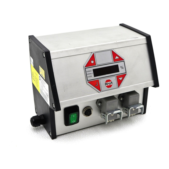
Controller for vibratory drive systems
Hide thumbs
Also See for ESK 2001:
- Operating instructions manual (17 pages) ,
- Operating instructions manual (24 pages) ,
- Operating instructions manual (23 pages)
Table of Contents
Advertisement
Advertisement
Table of Contents

Subscribe to Our Youtube Channel
Related Manuals for RNA ESK 2001


Summary of Contents for RNA ESK 2001
- Page 1 Operating Instructions Controller for vibratory drive systems ESK 2001...
-
Page 2: Table Of Contents
Table of Contents About this document ......................4 Safety directives ........................4 2.1. Design of safety directives ....................4 2.2. Fundamental safety directives .................... 4 2.3. Personnel ..........................4 2.4. Intended use ........................5 2.5. Residual hazards ........................ 5 2.5.1. Device .......................... - Page 3 Declaration of Conformity According to the Low-Voltage Directive 2014/35/EU and Electromagnetic Compatibility Directive 2014/30/EU We hereby declare that the product meets the following requirements: Low-Voltage Directive 2014/35/EC Electromagnetic Compatibility Directive 2014/30/EU The following harmonized standards have been applied: DIN EN 60204 T1, EN 61439-1 See separate Declaration of Conformity provided on delivery Remarks: The controllers have been manufactured in accordance with the Low Voltage Directive 2014/35/EU and are thus EMC-...
-
Page 4: About This Document
1. About this document Attention Read this document carefully and observe the safety directives before commencing any work. Document description: This document provides assistance in choosing your product. You will also find information on mechanical and electri- cal installation, operation, product extensions and accessories. Non-observance may cause trouble with the product or the environment, reduce the product lifetime or lead to other damage. -
Page 5: Intended Use
Use of the product in living areas may lead to EMC disturbance. The user is responsible for taking inter- ference suppression measures. • They are optimised for operation of RNA bowl feeders and linear feeders. Observe the limits indicated in the technical specification. Attention! •... -
Page 6: Product Information
3. Product information 3.1. Characteristic features The compact controller is designed for operation of a combination of bowl feeder and linear feeder or bowl feeder and hopper. Channel 2 can be switched over to belt drive. The unit offers the following characteristic features: •... -
Page 7: Accessories
4.1. Modes of operation RNA vibratory drive systems employ mechanical spring vibrators which are set to a vibrating frequency near the mains frequency or near double mains frequency depending on weight and/or size. This is why two modes of operation are possible:... -
Page 8: Automatic Mode Change
Vibratory drive systems by RNA do not require the operator to take care of selecting the right operating mode. The op- erating mode is determined by a code in the RNA vibrating drive connector. A wire jumper from pin 3 to 4 in the con- nector switches the controller to mode 2: 100 or 120 Hz. -
Page 9: Sensor Connection
4.4. Sensor connection The controller has two sensor inputs which can be used for accumulation checking and/or level monitoring purposes. You can connect sensors of type NPN or PNP. Floating con- (optical EGF40 tact sensor w/o am- Proximity switch Proximity plifier) General PNP switch General... -
Page 10: Status Outputs And Relays
4.5. Status outputs and relays The status outputs are used for remote diagnostics of the controller status or of the links of several controllers with one another. They are designed as freely available NPN-doped transistor circuits and they are floating. With the status output READY the transistor circuit is switched through whenever the controller is connected to power supply and switched on by its power switch closed. -
Page 11: Starting-Up The Controller
The controller display (membrane keypad) On / Off Pressing this button switches off all connected devices. The display shows "OFF". The controller remains ready for operation. Cursor up and cursor down Use these buttons to scroll through the controller menu or set the parameters. Enter Press this button to acknowledge the parameters entered with the cursor. -
Page 12: Description Of Individual Codes For Controller Programming
Calling-up the software version KANAL l KANAL 2 CODE Definition: 411. 57. 10. 23.11.99 Device type: Date 59 = ESK 2001 Version No. 58 = ESG 2001 Device type 57 = ESK 2000 Internal No. 56 = ESG 2000 Setting the feed rate by external voltage input 0-10V or potentiometer... - Page 13 application-specific settings, if previously saved. Rhein-Nadel Automation GmbH VT-BA-ESK2001_EN-2019 / 22.08.2019 SJ...
-
Page 14: Application-Specific Change Of Default Settings
KANAL 2 main menu CODE (*) For RNA feeders with 200 V magnets = 90 % 1) Only for channel 2: After removal of the enabling signal channel 2 switches off with a delay (5 minutes). 5.5.2. Code C003 Seal setpoint Objective: Sealing-in the setpoints in the main menu. -
Page 15: Code C006 Sensor Linkage
5.5.4. Code C006 Sensor linkage Objective: Linking of the two previously activated sensor inputs. Select code Set code KANAL l KANAL 2 CODE Code C006 KANAL l KANAL 2 CODE You can activate only one of the eight sensor links at a time. AND logic with blowing-off I = active KANAL l... -
Page 16: Code C008 Cycle Monitoring
Min/Max logic of the two sensor inputs. The bowl feeder stops when both sensors are operated. The vibratory feeder (channel 1) will re-start only after both sensors are cleared again. Relay K1 operates on stopping of bowl feeder. Relay K2 operates 4 sec. later (stopping the blowing air) AND / S2 logic Vibratory feeder (channel 1) stops when both sensors are operated. -
Page 17: Code C009 Show Status
5.5.6. Code C009 Show status Objective: Checking of the set vibrating frequency and of the sensor inputs. Select code Set code KANAL l KANAL 2 CODE Code C009 KANAL l KANAL 2 CODE I = active External enabling signal KANAL l 0 = not active KANAL 2 Channel 1... -
Page 18: Code C143 Saving Parameters
Attention! Before opening the device be sure to observe the safety directives in chapter 2. 5.5.9. Code C143 Saving parameters Objective: Saving of application-specific parameters Select code Select code KANAL l KANAL 2 CODE Code C143 KANAL l KANAL 2 CODE Save KANAL l... -
Page 19: Connection Diagram
7. Connection diagram Rhein-Nadel Automation GmbH VT-BA-ESK2001_EN-2019 / 22.08.2019 SJ... - Page 20 RNA Group Headquarters Manufacturing and Sales Further manufacturing sites of the RNA Group Rhein-Nadel Automation GmbH Reichsweg 19-23 Manufacturing D-52068 Aachen Lüdenscheid branch Phone: +49 (0) 241-5109-0 Rhein-Nadel Automation GmbH Fax: +49 (0) 241-5109-219 Nottebohmstraße 57 E-Mail: vertrieb@RNA.de D-58511 Lüdenscheid www.RNA.de...
Need help?
Do you have a question about the ESK 2001 and is the answer not in the manual?
Questions and answers