RNA ESR 2000 Operating Instructions Manual
Control units for vibratory drives
Hide thumbs
Also See for ESR 2000:
- Operating instructions manual (17 pages) ,
- Operating instructions manual (21 pages) ,
- Operating instructions manual (26 pages)

Related Manuals for RNA ESR 2000


Summary of Contents for RNA ESR 2000
- Page 1 Operating Instructions for the Control Units for Vibratory Drives Type ESR 2000 Rhein-Nadel Automation GmbH Rhein-Nadel Automation GmbH 14.04.2014 VT-BA ESR2000-GB...
- Page 2 Table of contents Chapt........................Page Technical datas....................Safety notes....................Commissioning instructions ................Operation Dimensional drawing..................Connection diagram..................Declaration of conformity as defined by Low voltage directive 2014/35/EU and EMC directive 2014/30/EU Herewith we declare that the product complies with the following provisions: Low voltage directive 2014/35/EU EMC directive 2014/30/EU applied harmonized standards:...
-
Page 3: Performance Characteristics
Status output (optocoupler): max. 30V DC 10mA, 2 voltage-fed open contact Relay contacts: max. 6A 250V AC Operating temperature: 0 ... 50° C Type of protection: IP 54 Accessoires RNA-Mat-code Label Denomination Type Manufacteur Supplier Connector Harting Coupler connector, 5-poles, straight... -
Page 4: Safety Instructions
Steps must be taken to ensure that all persons working with this control unit are familiar with the safety regulations and observe them. The device described in this manual is a control unit for operating RNA bowl feeders and linear feeders. The limit values specified in the technical data must be observed. -
Page 5: Operating Mode
OPERATING MODE To avoid mechanical and/or electrical damage occurring to the ESR 2000 control or connected equipment, the parameters listed in the tables below must be strictly adhered to. If you cannot find your particular type of drive unit listed in the tables then contact RNA AUTOMATION for advice. -
Page 6: Initial Setup
Please note that all parameters of the controller are tuned up to the bowl feeder if supplied as a package with an ESR 2000 unit and in parameter 143 User 0.3 stored. All settings are stored and retrievable. Reconfigurations, exchange of controllers or mechanical alterations may cause damages to... - Page 7 Failure to heed above mentioned warnings can be lead to destroy the feeding equipment or parts thereof. In this case all waranty claimes cease to exist. After the first adjustment is succesfull, you can set the sensor inputs and the soft run or stopping time. Sensor Inputs and Sensor Links The control unit has two built-in sensor inputs.
- Page 8 Housing XS 3 / Y - Cable as a distribution XS 3.2 / XS 3.1 / Termination of a sensor and a contact by adapter. Fig.: Connecting diagram for sensors on 2-way distributor Housing XS 3 / Y - Cable as distrubution XS 3.2 / XS 3.1 / Amplifierless photocell with externall preresistor 1.8 kOhms, 0.25W...
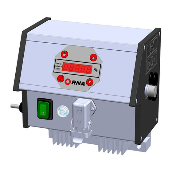
- Page 9 Operation General ON/ OFF Cursor up Return Cursor down XS 3 XS 4 Main power switch Channel 1 Control unit plug connections Mains power The control unit is isolated from the mains with a double-pole switch. switch Plug connector for sensors XS 3 Plug connector for bowl feeder or linear feeder ( <...
-
Page 10: Switching On The Control Unit
Switching on the Control Unit Switch on the control unit with the mains power switch. The main menu will appear in the display showing the last setpoint set in channel 1 (Bowl feeder or linear feeder feed rate). KANAL l KANAL 2 CODE The following displays may also appear depending on the circuit state of the unit. - Page 11 Programmed application examples KANAL l KANAL 2 CODE Call memorized settings P1-10 based on application examples. (ask for our catalogue fax 0241/5109-219 or by Internet www.rna.de) Output preset with an external voltage. 0-10V or potentiometer KANAL l KANAL 2 CODE...
- Page 12 Operating Frequency KANAL l KANAL 2 35 - 140 CODE (see 3.1 Operating Mode) Return Store and return to KANAL l KANAL 2 main menu CODE 4.5.2 Code C003 Lock Setpoint Aim: Blocking the setpoints in the main menu. The values can no longer be changed directly. Changes can only be made using code C001.
- Page 13 I = active Level control KANAL l 0 = inactive KANAL 2 CODE I = active Single link KANAL l KANAL 2 0 = inactive CODE Return Store and return to the KANAL l KANAL 2 CODE main menue A brief description of the individual links And (AND) link of the two sensor inputs with blow-off of the outlet tracks.
- Page 14 Switch off channel 1 I = see below KANAL l KANAL 2 0 = see below CODE I = warning at relay K1 Switch (Relay K1) KANAL l 0 = warning at relay K2 KANAL 2 CODE Return Store and return to KANAL l KANAL 2 main menu...
- Page 15 Select code Select code KANAL l KANAL 2 CODE Code C100 KANAL l KANAL 2 CODE External supply channel 1 I = active KANAL l 0 = inactive KANAL 2 CODE Return Store and return to KANAL l KANAL 2 main menu CODE If the external supply is activated, the last set digital output value (%) will be the minimum output for 0...
- Page 16 US.PA. Selection and confirmation of US.PA restores the user parameters previously stored under C143. Rhein-Nadel Automation GmbH 14.04.2014 VT-BA ESR2000-GB...
-
Page 17: Scale Drawing
4.5.11 Failure In case of failure, the controller shut-off automatically showing a flashing „ERROR“ text. The error signal is stored even on disconnecting the line up to the momemt when the error indication is cleared in C009. Overload limiting ERROR KANAL l KANAL l KANAL 2... -
Page 18: Connecting Diagram
Connecting Diagram External rated value 0-10 VDC External potentiometre Load max. 6A Mains supply Contact - load max. 6 A, 250 V AC 230 V; 50/60 Hz Rhein-Nadel Automation GmbH 14.04.2014 VT-BA ESR2000-GB... - Page 19 Rhein-Nadel Automation GmbH Reichsweg 19/23 D - 52068 Aachen Tel (+49) 0241/5109-159 Fax +(49) 0241/5109-219 Internet www.rna.de Email vertrieb@rna.de Rhein-Nadel Automation GmbH Zweigbetrieb Lüdenscheid Nottebohmstraße 57 D - 58511 Lüdenscheid Tel (+49) 02351/41744 Fax (+49) 02351/45582 Email werk.luedenscheid@rna.de...
Need help?
Do you have a question about the ESR 2000 and is the answer not in the manual?
Questions and answers