Table of Contents
Advertisement
Quick Links
Advertisement
Table of Contents

Related Manuals for RNA ESR 3000 Series


Summary of Contents for RNA ESR 3000 Series
- Page 1 Operating Instructions Controllers for Vibratory Drive Systems ESR 3000 ESM 3000...
-
Page 2: Table Of Contents
Table of Contents General ..........................6 1.1. EC conformity ........................7 Function ..........................7 2.1. Level control (accumulation control) ..................7 2.2. Operation with two speeds (2nd setpoint for coarse / fine switchover) ........8 2.3. Control inputs and outputs ..................... 8 Enabling input....................... - Page 3 Dimensions - cabinet-mounting version ESM3000/6A ............23 Dimensions of cabinet-mounting version -ESM3000/16A ............ 24 Annex - Service ........................25 17.1. Service menu ......................... 25 17.2. Frequency setting range ....................25 17.3. Current limiting ......................26 Rhein-Nadel Automation GmbH VT-BA-ESR-ESM3000-EN_2021.docx / 15 March 2021...
- Page 4 Declaration of Conformity According to the Low-Voltage Directive 2014/35/EU and Electromagnetic Compatibility Directive 2014/30/EU We hereby declare that the product meets the following requirements: Low-Voltage Directive 2014/35/EU Electromagnetic Compatibility Directive 2014/30/EU Applied harmonised standards: DIN EN 60204 T1 EN 61439-1 Remarks: Rhein-Nadel-Automation ---------------------------------...
- Page 5 Safety Directives for the User These instructions contain the information required to use the products described correctly. The information is intended for technically qualified workers. Qualified workers are people who, due to their professional training, experience and schooling, as well as their knowledge of relevant standards, provisions, accident prevention regulations and operating conditions, have been authorized by the person responsible for the safety of the equipment to perform the required tasks and who can recognize and avoid potential hazards (definition for skilled persons according to IEC...
-
Page 6: General
General The controllers of the ESR 3000 / ESM 3000 series are specially adapted variable frequency drive units for vibratory feeder control. The devices generate a mains independent output frequency for the vibratory feeder. Therefore an exact tuning of the springs or weight compensation are not required. The sinusoidal output current provides for smooth operation of the feeder. -
Page 7: Ec Conformity
1.1. EC conformity The controller is compliant with the following standards: EC EMC Directive 2014/30/EU EC Low Voltage Directive 2014/35/EU Applied harmonised standards: DIN EN 60204, part 1 EN 61439-1 Function The device is operated via a control panel on the front (keys and LED display). All settings can be made via menus displayed on this control panel. -
Page 8: Operation With Two Speeds (2Nd Setpoint For Coarse / Fine Switchover)
2.2. Operation with two speeds (2nd setpoint for coarse / fine switchover) Instead of the level control feature you can also use coarse/fine function (menu ‘C 003’). Switchover to the second setpoint takes place via the sensor input that is otherwise used for level control. Switchover can be activated via a contact or an external 24 V DC signal voltage. -
Page 9: Design
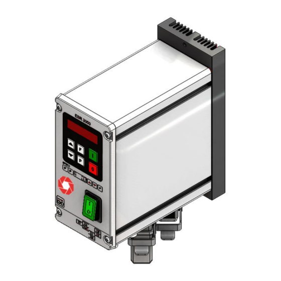
Design The devices are available as stand-alone add-on units or as cabinet-mounting units. 3.1. Add-on device • Power switch • Control and display panel • Mains connection cable with grounding-type plug. • Output socket-outlet for connection of feeder. Sensor socket-outlet. Standard configuration includes 24 V DC sensors with PNP output. 3.2. -
Page 10: Order Designation (Standard Devices)
Order designation (standard devices) Designation Design ESR 3000 / 6 A – IP54 6 A, housing design with level control ESR 3000 / 12A – IP 54 12 A, housing design with level control ESM 3000 / 6A – IP20 6 A, cabinet built-in design with level control ESM 3000 /16A –... -
Page 11: Operator Controls
Operator controls DISPLAY ANZEIGE BACK ZURÜCK AUFWÄRTS ABWÄRTS DOWN PROGRAMM PROGRAM MODUS / BESTÄTIGEN MODE / CONFIRM 7.1. Setting behaviour Operation and set-up of the device is via a six-button control pad with LED display on the front panel. All settings related to operating modes as well as to adjustable parameters can be made via this control pad. -
Page 12: Commissioning
Commissioning 8.1. Place of installation Attention Take care to install the devices on a surface which is as vibration-free as possible. Be sure that there is sufficient air circulation. 8.2. Preparatory measures • Check whether the local mains voltage matches the device voltage (indication on the rating plate) and whether the connection value of the feeder is within the admissible voltage range. -
Page 13: Setting
Basic setting: • Connect feeder. • Set frequency (see feeder data). Menu ‘C 096’, parameter ‘F’. • Check current limit (see feeder data) in menu ‘C 040’, parameter ‘I’ (indicates the current limit in % of the maximum current). Adjust value in the Service menu if necessary. •... -
Page 14: Adjustment To The Feeder
9.2. Adjustment to the feeder Feeder settings Code C. 020, 096 Förderleistung 0...100 % Feed rate 0...100% Maximalbegrenzung 100...5 % Maximum limitation 100...5 % Schwingfrequenz [Hz] Vibrating frequency [Hz] Sanftanlaufzeit Soft start time Sanftauslaufzeit Soft stop time Betriebsmodus Operating mode Adjust maximum limitation 1. -
Page 15: Sensor Timeout
Sensor timeout Code C. 015 0 = Störungszeit nicht aktiv 0 = fault time not active I = Störungszeit aktiv I = fault time active E = sensor timeout time (sec.) E. = Sensor-Time-out Zeit [sek] Ai. = Nachlaufzeit Ventilausgang Ai. -
Page 16: Determining The Resonance Frequency
Determining the resonance frequency Manual adjustment of the vibrating frequency Be sure to adjust the output frequency with a low setpoint setting, as a high vibrating amplitude may occur already at low output voltage when you hit the resonance frequency. To determine the resonance fre- quency, an analog pointer-type r.m.s. -
Page 17: Reset Error Messages / Error
Reset error messages / ERROR Errors are signalled by alternating indication of ‘ERROR’ and of the respective error code Overload limitation Output power exceeded, e.g. incorrect frequency setting, air gap too big. Short circuit cut-out Damaged magnet, ground fault, damaged cable. Overvoltage Mains voltage too high or energy returned by the magnet in case of low frequencies. -
Page 18: Connection Of Enclosed Version
Connection of enclosed version Internal connection 6 A, 12 A devices If a potentiometer is connected, set parameter ‘POT.’ = I in menu ‘C 003’. 1 2 3 4 5 6 7 31 32 33 34 35 36 37 21 22 23 24 25 26 27 28 29 Magnet... -
Page 19: 11.1. Connection Housing Design 12 A
11.1. Connection housing design 12 A 1 = +24 V Ausgang + 24 V output 3 = GND X4 Sensor Stauschaltung X4 accumulation control 4 = +24 V Eingang +24 V input sensor 1 = +24 V Ausgang +24 V output X40 vibration amplitude 2 = Eingang Input... -
Page 20: Connection Of Cabinet-Mounting Version (6 A)
Connection of cabinet-mounting version (6 A) 6A, IP 20 ESM 3000 Feedstock sensor Material-Sensor +24V Enable Freigabe 12...24V, DC Sollwert Setpoint 0(4)...20mA 0...10V R=500 OHM schwarz black External extern INPUT orange SW... + 24V SPEED Acceleration Beschleunigungs- sensor Sensor Abschirmung Shielding Internal status internes... -
Page 21: Connection Of Cabinet-Mounting Version (16 A)
Connection of cabinet-mounting version (16 A) ESM 3000/16 Input voltage Eingangsspannung L, N, PE, 110 /240V 50/60Hz Feedstock sensor Material-Sensor 12...24V, DC +24V Enable Freigabe Setpoint 0...10V Sollwert 0(4)...20mA SPEED +10V black schwarz Acceleration Beschleunigungs- orange INPUT SW... sensor sensor + 24V Förderer Feeder... -
Page 22: Dimensions Of Enclosed Version
Dimensions of enclosed version Enclosed version 6A Enclosed version 12A Rhein-Nadel Automation GmbH VT-BA-ESR-ESM3000-EN_2021.docx / 15 March 2021... -
Page 23: Dimensions - Cabinet-Mounting Version Esm3000/6A
Dimensions - cabinet-mounting version ESM3000/6A Rhein-Nadel Automation GmbH VT-BA-ESR-ESM3000-EN_2021.docx / 15 March 2021... -
Page 24: Dimensions Of Cabinet-Mounting Version -Esm3000/16A
Dimensions of cabinet-mounting version -ESM3000/16A Ø5,0 ESM 3000/16 LP 1311 SPEED +10V Rhein-Nadel Automation GmbH VT-BA-ESR-ESM3000-EN_2021.docx / 15 March 2021... -
Page 25: Annex - Service
Annex - Service Attention! The settings in the Service menu described here must only be made by trained specialists as they the function and limit values of the feeders. The supplier of the machine can decide whether to pass on this information or reserve it for supplier’s service personnel. This menu cannot be accessed directly in the normal menu structure, but has to be enabled via an addi- tional key code. -
Page 26: 17.3. Current Limiting
17.3. Current limiting With the current limitation the maximum output current of the control is limited to the admissible solenoid is set with parameter ‘I’. The setting in the display is made in percent current I . The current limitation I of the nominal current of the device I ( 100% corresponds to the nominal current of the device). - Page 27 Headquarter Rhein-Nadel Automation GmbH Reichsweg 19-23 D-52068 Aachen Tel.: +49 (0)241-5109-0 E-Mail: vertrieb@RNA.de www.RNA.de Further manufacturing sites Further RNA group companies: of the RNA Group: Lüdenscheid branch PSA Zuführtechnik GmbH Rhein-Nadel Automation GmbH Steinäckerstraße 7 Nottebohmstraße 57 D-74549 Wolpertshausen D-58511 Lüdenscheid Tel.: +49 (0)7904-94336-0...
Need help?
Do you have a question about the ESR 3000 Series and is the answer not in the manual?
Questions and answers