Table of Contents
Advertisement
Quick Links
Advertisement
Table of Contents

Related Manuals for RNA SCU2000


Summary of Contents for RNA SCU2000
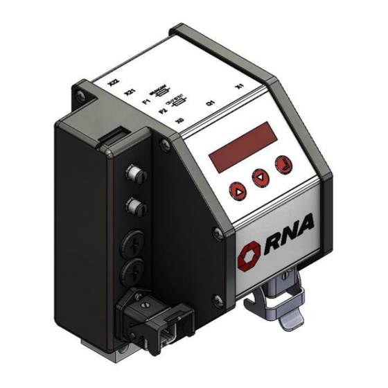
- Page 1 Operating Instructions Controllers Vibratory Drive Systems SCU2000...
-
Page 2: Table Of Contents
Degree of protection - Protection of persons and equipment ........6 Product information ........................ 6 3.1. Functional description ...................... 6 3.2. Difference between SCU1000 and SCU2000 ..............6 3.3. Technical data ........................7 3.4. Products, spare parts and accessories ................8 Notes on start-up ........................ - Page 3 Declaration of Conformity According to the Low-Voltage Directive 2014/35/EU and Electromagnetic Compatibility Directive 2014/30/EU We hereby declare that the product meets the following requirements: Low-Voltage Directive 2014/35/EC Electromagnetic Compatibility Directive 2014/30/EU Applied harmonised standards: DIN EN 60204 T1 EN 61439-1 Remarks: Rhein-Nadel-Automation ---------------------------------...
-
Page 4: About This Document
Read this document carefully and observe the safety directives before commencing any work. The information given in this document reflects the following version: Product from software version Date SCU2000 V1.0 2019-03-01 1.1. Document description: This document provides assistance in choosing your product. You will also find information on mechanical and electrical installation, product extensions and accessories. -
Page 5: Intended Use
Use of the product in living areas may lead to EMC disturbance. The user is responsible for taking interference suppression measures. • They are optimised for operation of RNA vibratory feeders and linear feeders. Observe the limits indicated in the technical specification. Attention! •... -
Page 6: Degree Of Protection - Protection Of Persons And Equipment
3.1. Functional description The compact controller can operate all RNA vibrating motors up to a load current of 6 amps. It is designed for individual installation right local to the vibrating drive. The controller is customized for RNA vibratory drive systems. The feed rate can be precisely adjusted within the setting range via LED display. -
Page 7: Technical Data
3.3. Technical data Technical data Power supply (can be changed internally): 230V AC, 50/60Hz, +10 -10% 115V AC, 50/60Hz, +10 -10% Output voltage: 40...208 V variable, (230V supply) 20...105 V variable, (115V supply) Load current: max. 6 A(I Device fusing (power input): 2x miniature fuse 5 x 20mm M6.3A/250V AC Operating modes:... -
Page 8: Products, Spare Parts And Accessories
Then check for proper operation while the output is increased. 4.1. Modes of operation RNA vibratory drive systems employ mechanical spring vibrators which are set to a vibrating frequency near the mains frequency or near double mains frequency depending on weight and/or size. -
Page 9: Automatic Mode Change
Vibratory drive systems by RNA do not require the operator to take care of selecting the right operating mode. The operating mode is determined by a code in the RNA vibrating drive connector. A wire jumper from pin 3 to 4 in the connector switches the controller to mode 2: 100 or 120 Hz. In the absence of this wire jumper the controller operates in mode 1: 50 or 60 Hz. - Page 10 For safety reasons the cable gland used must be plastic. It is not permitted to enlarge the existing hole or otherwise modify the housing. Connection of external enabling signal to SCU2000 via floating contact Attention! Any work on electrical equipment shall be carried out exclusively by a professional electrician, or by instructed persons working under the direction and supervision of a professional electrician, according to electrotechnical rules.
-
Page 11: Status Signals To An External Controller
Observe the safety directives in chapter 2. SCU2000: 7 = enabling via external contact 8 = enabling via external contact Connection for external enabling signal: Disconnect the device from power supply. Open left side of the device Remove the upper blanking plug (M16x1.5) Fit a plastic cable gland (M16x1.5) in the existing hole... -
Page 12: Changing The Supply Voltage
Blue Active Black See also connection diagram of SCU2000, chapter 5. 4.5. Changing the supply voltage The controller is designed to operate both on 230V, 50/60Hz and on 115V, 50/60Hz. The given operating voltage must be set on the selector switch in the controller. -
Page 13: Measuring The Output Voltage Or Output Current
The measuring adapter is fitted with appropriate connectors for easy connection between controller and vibrating drive. The use of moving-iron measuring instruments makes sure that the true root mean square value is measured. 5. Connections on the controller 5.1. SCU2000 Status output Enabling input Access to fuses Power supply con-... -
Page 14: Scu2000 Connection Diagram
6. SCU2000 connection diagram External enabling External enabling active ready contact 24VDC Supply Drive voltage selector max. 6A ready active floating contact PLC output Attention! Connectors X21 and X22. Controllers with serial numbers before A889494 came with female connectors. Controllers with serial number A889494 and higher come with male connectors (see connection diagram above). -
Page 15: Operation Of Scu2000
7. Operation of SCU2000 LED display: A short while after starting of the controller the status display comes up and the set feed rate is shown. 75.0 Other potential display readings: STOP External enabling signal missing or wrong parameter assignment. -
Page 16: Scu2000 Menu Structure
7.1. SCU2000 menu structure Display Display: Boost factor ≠ 1.0 (for full-wave only) Output inhibited by missing enabling signal Down ENTER Status display Schnellmenü Förderleistung 0...100 % 0 … 100 % feed rate 0 … 100 % Förderleistung 0...100 %... -
Page 17: Description Of Scu2000 Parameters
7.2. Description of SCU2000 parameters Attention Setting of wrong parameters may result in electrical or mechanical damage to the controller or vibrating motor. Therefore, set a low feed rate on the controller before starting. Then check for proper operation while the output is increased. -
Page 18: Dimensional Drawing Of Scu2000
8. Dimensional drawing of SCU2000 All dimensions in mm Rhein-Nadel Automation GmbH VT-BA-SCU2000_EN_2023.docx... - Page 19 Headquarters Rhein-Nadel Automation GmbH Reichsweg 19-23 D-52068 Aachen Phone: +49 (0)241-5109-0 E-mail: vertrieb@RNA.de www.RNA.de Further manufacturing sites Further RNA group companies: of the RNA Group Lüdenscheid site PSA Zuführtechnik GmbH Rhein-Nadel Automation GmbH Steinäckerstraße 7 Nottebohmstraße 57 D-74549 Wolpertshausen D-58511 Lüdenscheid...
Need help?
Do you have a question about the SCU2000 and is the answer not in the manual?
Questions and answers