RNA ESR 2000 Operating Instructions Manual
Controllers for vibratory drive systems
Hide thumbs
Also See for ESR 2000:
- Operating instructions manual (20 pages) ,
- Operating instructions manual (17 pages) ,
- Operating instructions manual (21 pages)
Table of Contents
Advertisement
Quick Links
Advertisement
Table of Contents

Related Manuals for RNA ESR 2000


Summary of Contents for RNA ESR 2000
- Page 1 Operating Instructions Controllers Vibratory Drive Systems ESR 2000...
-
Page 2: Table Of Contents
Table of Contents About this document ......................4 Safety information ........................4 2.1. Design of safety directives ....................4 2.2. Fundamental safety directives ..................4 2.3. Personnel ......................... 4 2.4. Intended use ........................5 2.5. Residual hazards......................5 2.5.1. Device ........................5 2.5.2. - Page 3 Declaration of Conformity According to the Low-Voltage Directive 2014/35/EU and Electromagnetic Compatibility Directive 2014/30/EU We hereby declare that the product meets the following requirements: Low-Voltage Directive 2014/35/EC Electromagnetic Compatibility Directive 2014/30/EU Applied harmonised standards: DIN EN 60204 T1 EN 61439-1 Note: Rhein-Nadel-Automation ---------------------------------...
-
Page 4: About This Document
1. About this document Attention Read this document carefully and observe the safety directives before commencing any work. Document description: This document provides assistance in choosing your product. You will also find information on mechanical and electrical installation, operation, product extensions and accessories. Non-observance may cause trouble with the product or the environment, reduce the product lifetime or lead to other damage. -
Page 5: Intended Use
Use of the product in living areas may lead to EMC disturbance. The user is responsible for tak- ing interference suppression measures. • They are optimised for operation of RNA bowl feeders and linear feeders. Observe the limits in- dicated in the technical specification. Attention! •... -
Page 6: Degree Of Protection - Protection Of Persons And Equipment
2.5.3. Degree of protection - Protection of persons and equipment • All specifications relate to installed condition ready for operation. • All slots not used must be closed by protection caps or dummy plugs in order not to reduce the pro- tection against accidental contact. -
Page 7: Technical Data
This is why the electrical operating conditions must be adapted to the vibrating system. The following table shows the variable safe operating ranges for the complete RNA product range. Attention Uniform weight distribution on the bowl (balancing) is a prerequisite for a consistent and stable feed rate. -
Page 8: Commissioning
When a bowl feeder is delivered complete with ESR 2000 controller the operating parameters are already set to suit the bowl feeder and stored in the 143 USER – 0 parameter. -
Page 9: Controller Set-Up To Suit A Vibratory Feeder
Attention: Improper start-up of a feeder after conversion, controller replacement or mechanical modification creates the risk of damage to springs, vibratory units, orienting devices or carryover devices. 3.5.2. Controller set-up to suit a vibratory feeder Procedure: 1. Read frequency range and max. load current from rating plate of the vibratory feeder. (See tables 1 and 2.) Connect controller to power supply and switch it on without vibratory feeder. -
Page 10: Sensor Inputs And Sensor Linkages
Vibrating drive operating 45 - 120 frequency Check the load current; it must not exceed the maximum value! The RNA - plug-in adapter ESZ-01 greatly facilitates start-up and, in particular, determination of the load current. Save the operating parameters chosen Return... -
Page 11: Sensor Connection
3.7. Sensor connection The controller has two sensor inputs which can be used for accumulation checking and/or level monitoring purposes. You can connect sensors of type NPN or PNP. 10K if req‘d EGF40 Floating contact (optical sensor w/o Proximity switch, Proximity switch, amplifier) general,... -
Page 12: Status Outputs And Relays
3.8. Status outputs and relays The status outputs are used for remote diagnostics of the controller status or of the links of several controllers with one another. They are designed as freely available NPN-doped transistor circuits and they are floating. With the status output READY the transistor circuit is switched through whenever the controller is connected to power supply and switched on by its power switch closed. -
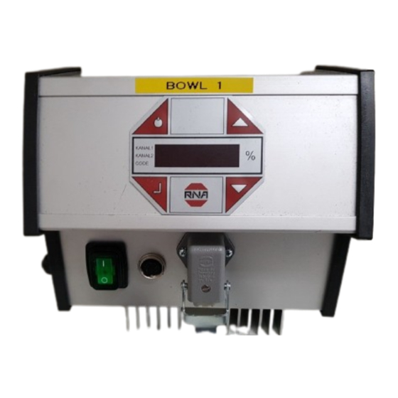
Page 13: The Controller Display (Membrane Keypad)
The controller display (membrane keypad) 4.1.2. On / Off Pressing this button switches off all connected devices. The display shows "OFF". The controller remains ready for operation. Cursor up and cursor down Use these buttons to scroll through the controller menu or set the parame- ters. -
Page 14: Description Of Individual Codes For Controller Programming
buttons (UP/DOWN). Press ENTER again to acknowledge the entries made. The decimal point is no longer blinking. Using the cursor buttons you can continue scrolling in the menu. Same procedure analogously ap- plies to the code menus described below. All the following display screens show the default setting. If the actual indication on the controller differs from what is shown here, the default setting has been changed in individual codes to suit a specific application. -
Page 15: Code C003 Seal Setpoint
Set vibrating amplitude 0 - 100 % KANAL l KANAL 2 CODE Limit vibrating amplitude 50 - 100 % (*) For RNA feeders with 100V/200V magnets 90% External enabling signal I = active 0 = not active External enabling signal... -
Page 16: Code C004 Sensor Input 1 And Code C005 Sensor Input 2
4.5.3. Code C004 sensor input 1 and code C005 sensor input 2 Objective: Activating and setting the sensor inputs Select code Set code KANAL l KANAL 2 CODE Code C004 Sensor 1 input I = active KANAL l KANAL 2 0 = not active CODE Invert input signal direc-... -
Page 17: Code C006 Sensor Linkage
4.5.4. Code C006 Sensor linkage Objective: Linking of the two previously activated sensor inputs. Select code Set code KANAL l KANAL 2 CODE Code C006 You can activate only one of the eight sensor links. AND logic with blowing off I = active KANAL l KANAL 2... - Page 18 OR logic of the two sensor inputs. Bowl feeder (channel 1) stops when one of the two sensors is operated. Orienting air can be switched off with delay (4 sec.) via relay K2. Min/Max logic of the two sensor inputs. The bowl feeder stops when both sensors are operated.
-
Page 19: Code C008 Cycle Monitoring
4.5.5. Code C008 cycle monitoring Objective: Monitoring of sensors 1 (accumulation check) and/or 2. When activating the cycle monitoring function, the "AND, SOL" links in code C006 must not be acti- vated!!! Select code Set code Code C008 Sensor input 1 is moni- I = active tored 0 = not active... -
Page 20: Code C009 Show Status / Reset Error Message
4.5.6. Code C009 Show status / Reset ERROR message Objective: Checking of the set vibrating frequency and of the sensor inputs. Select code Set code Code C009 Clear Error Reset error mes- KANAL l KANAL 2 sage CODE External enabling signal I = active channel 1 0 = not active... -
Page 21: Code C100 Setting The Feed Rate By External Voltage Input
4.5.8. Code C100 Setting the feed rate by external voltage input. Objective: Setpoint change by external voltage Select code KANAL l Select code KANAL 2 CODE Code C100 KANAL l KANAL 2 CODE External voltage applica- I = active KANAL l KANAL 2 tion to channel 1 0 = not active... -
Page 22: Code C210 Retrieving Parameters
4.5.10. Code C210 Retrieving parameters Objective: Resetting to default values or retrieving stored application-specific settings Select code Set code Code C210 Factory setting KANAL l KANAL l KANAL 2 KANAL 2 CODE CODE Select memory location 0- Select the memory location Load parameters Return... -
Page 23: Error Messages
4.5.11. Error messages If a fault occurs during operation the controller switches itself off automatically and the display shows ER- ROR and a brief message text blinking in alternate succession. The controller keeps this error message in the memory even after disconnection from power supply until the message is reset in C009. Overload limitation The output is above the admissible limit. -
Page 24: Dimensioned Drawing
5. Dimensioned drawing Rhein-Nadel Automation GmbH VT-BA-ESR2000_EN_2023.docx... -
Page 25: Connection Diagram
6. Connection diagram Rhein-Nadel Automation GmbH VT-BA-ESR2000_EN_2023.docx... - Page 26 Headquarters Rhein-Nadel Automation GmbH Reichsweg 19-23 D-52068 Aachen Phone: +49 (0)241-5109-0 E-mail: vertrieb@RNA.de www.RNA.de Further manufacturing sites Further RNA group companies: of the RNA Group Lüdenscheid site PSA Zuführtechnik GmbH Rhein-Nadel Automation GmbH Steinäckerstraße 7 Nottebohmstraße 57 D-74549 Wolpertshausen D-58511 Lüdenscheid...
Need help?
Do you have a question about the ESR 2000 and is the answer not in the manual?
Questions and answers