Table of Contents
Advertisement
Advertisement
Table of Contents

Related Manuals for RNA SCU1000


Summary of Contents for RNA SCU1000
- Page 1 Operating Instructions Controller for vibratory drive systems SCU1000 SCU2000...
-
Page 2: Table Of Contents
SCU1000 & SCU2000 connection diagram................15 Operation of SCU1000 & SCU2000 ..................16 7.1. Menu structure of SCU1000 & SCU2000 ................17 7.2. Description of SCU1000 & SCU2000 parameters ............... 18 Installation of I/O retrofit kit into SCU1000 ................19 Dimensional drawing of SCU1000 .................. - Page 3 We hereby declare that the product meets the following requirements: Low-Voltage Directive 2014/35/EC Electromagnetic Compatibility Directive 2014/30/EU Applied harmonised standards: DIN EN 60204 T1 EN 61439-1 Remarks: Rhein-Nadel-Automation --------------------------------- Managing Director Jack Grevenstein Rhein-Nadel Automation GmbH VT-BA-SCU1000-2000-EN_2019 / 27.06.2019 SJ...
-
Page 4: About This Document
They know all regulations for the prevention of accidents, directives and laws applicable to set-up, installa- tion and commissioning on site, and they are able to apply the same. • They have knowledge and skills of First Aid. Rhein-Nadel Automation GmbH VT-BA-SCU1000-2000-EN_2019 / 27.06.2019 SJ... -
Page 5: Intended Use
Use of the product in living areas may lead to EMC disturbance. The user is responsible for taking inter- ference suppression measures. • They are optimised for operation of RNA vibratory feeders and linear feeders. Observe the limits indicated in the technical specification. Attention! •... -
Page 6: Product Information
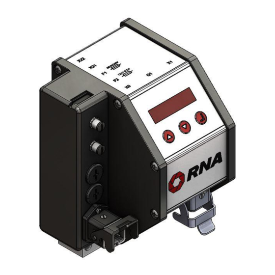
Functional description The compact controller can operate all RNA vibrating motors up to a load current of 6 amps. It is designed for individ- ual installation right local to the vibrating drive and customized for RNA vibratory drive systems. The feed rate can be precisely adjusted within the setting range via LED display. -
Page 7: Technical Data
Any intervention on the controller shall void the manufacturer's warranty. This does not apply to proper installation of the I/O retrofit kit proper change of supply voltage proper connection of external enabling signal in accordance with these operating instructions. Rhein-Nadel Automation GmbH VT-BA-SCU1000-2000-EN_2019 / 27.06.2019 SJ... -
Page 8: Products, Spare Parts And Accessories
Measuring adapter Accessory for measurement of output voltage and output current. 31002525 ESZ-02 The adapter is supplied with connectors. (400V/10A) I/O retrofit kit Accessory for SCU1000 for retrofitting the enabling and status 31002801 signals Rhein-Nadel Automation GmbH VT-BA-SCU1000-2000-EN_2019 / 27.06.2019 SJ... -
Page 9: Notes On Start-Up
Vibratory drive systems by RNA do not require the operator to take care of selecting the right operating mode. The op- erating mode is determined by a code in the RNA vibrating drive connector. A wire jumper from pin 3 to 4 in the con- nector switches the controller to mode 2: 100 or 120 Hz. -
Page 10: Start/Stop By External Controller
For both external enabling options the signal cables must be connected to terminal block X2 inside the controller. Remove the blanking plug from one of the two top holes and install the M8x1 cable gland (supplied with the SCU1000) with lock nut. Insert a cable with a cross-section of 2x0.25mm² min. to 2x0.5mm² max. The max. cable diameter is 5mm. - Page 11 It is not permitted to enlarge the existing hole or otherwise modify the housing. External enabling parameter assignment. The external enabling functionality must be set by the Hi parameter in the parameters menu. See chapter 6. Rhein-Nadel Automation GmbH VT-BA-SCU1000-2000-EN_2019 / 27.06.2019 SJ...
-
Page 12: Status Signals To An External Controller (Scu2000 Only)
See also connection diagram of SCU2000, chapter 5. If you need the enabling signal and status signals of the SCU1000 at a later date, the connections can be made ac- cessible by installation of an I/O retrofit kit. See Chapter 8. -
Page 13: Measuring The Output Voltage Or Output Current
The measuring adapter is fitted with appropriate connectors for easy connection between controller and vibrat- ing drive. The use of moving-iron measuring instruments makes sure that the true root mean square value is meas- ured. Rhein-Nadel Automation GmbH VT-BA-SCU1000-2000-EN_2019 / 27.06.2019 SJ... -
Page 14: Connections On The Controller
Access to fuses Power supply connector Connection for Power switch vibratory feeder Attention! When replacing the fuse be sure to use the specified rating of M6.3A/250V. Too high a fuse rating may destroy the controller. Rhein-Nadel Automation GmbH VT-BA-SCU1000-2000-EN_2019 / 27.06.2019 SJ... -
Page 15: Scu1000 & Scu2000 Connection Diagram
6. SCU1000 & SCU2000 connection diagram external re- external re- lease 24VDC lease contact Supply Drive voltage selector max. 6A PLC output floating contact external re- external re- active ready lease contact lease 24VDC Drive Supply voltage selector max. 6A... -
Page 16: Operation Of Scu1000 & Scu2000
7. Operation of SCU1000 & SCU2000 LED display: A short while after starting of the controller the status display comes up and the set feed rate is shown. 75.0 Other potential display readings: STOP External enabling signal missing or wrong parameter assignment. -
Page 17: Menu Structure Of Scu1000 & Scu2000
7.1. Menu structure of SCU1000 & SCU2000 Display: Display Boost factor ≠ 1.0 (for full-wave only) Output inhibited by missing enabling signal Down ENTER feed rate 0 … 100 % Status display Schnellmenü Förderleistung 0...100 % feed rate 0 … 100 % Förderleistung 0...100 %... -
Page 18: Description Of Scu1000 & Scu2000 Parameters
7.2. Description of SCU1000 & SCU2000 parameters Attention Setting of wrong parameters may result in electrical or mechanical damage to the controller or vibrating motor. Therefore, set a low feed rate on the controller before starting. Then watch proper operation while the out- put is increased. -
Page 19: Installation Of I/O Retrofit Kit Into Scu1000
8. Installation of I/O retrofit kit into SCU1000 Attention Any work on electrical equipment shall be carried out exclusively by a professional electrician, or by in- structed persons working under the direction and supervision of a professional electrician, according to electrotechnical rules. -
Page 20: Dimensional Drawing Of Scu1000
9. Dimensional drawing of SCU1000 All dimensions in mm Rhein-Nadel Automation GmbH VT-BA-SCU1000-2000-EN_2019 / 27.06.2019 SJ... -
Page 21: Dimensional Drawing Of Scu2000
Dimensional drawing of SCU2000 All dimensions in mm Rhein-Nadel Automation GmbH VT-BA-SCU1000-2000-EN_2019 / 27.06.2019 SJ... - Page 22 Fax: +41 (0) 62 956 10-10 E-mail: info@handling-systems.ch www.handling-systems.ch Manufacturing and Sales Pol. Ind. Famades c/Energia 23 E-08940 Cornella de Llobregat (Barcelona) Spain Phone: +34 (0)93 377-7300 Fax::+34 (0)93 377-6752 E-Mail: info@vibrant-RNA.com www.vibrant-RNA.com www.vibrant.es Rhein-Nadel Automation GmbH VT-BA-SCU1000-2000-EN_2019 / 27.06.2019 SJ...
Need help?
Do you have a question about the SCU1000 and is the answer not in the manual?
Questions and answers