Table of Contents
Advertisement
Advertisement
Table of Contents

Related Manuals for RNA ESR 3000 Series


Summary of Contents for RNA ESR 3000 Series
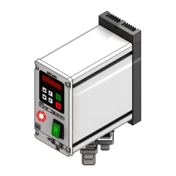
- Page 1 Operating Instructions Controller for vibratory drive systems ESR 3000 ESM 3000...
-
Page 2: Table Of Contents
Table of Contents General ..........................5 1.1. EC Conformity........................5 Function ..........................6 2.1. Track control ........................6 2.2. Operating with two speeds (2 set points for coarse/fine switching) ........6 2.3. Control inputs and output ....................6 2.3.1. Enable input ......................... 6 2.3.2. - Page 3 Declaration of Conformity According to the Low-Voltage Directive 2014/35/EU and Electromagnetic Compatibility Directive 2014/30/EU We hereby declare that the product meets the following requirements: Low-Voltage Directive 2014/35/EC Electromagnetic Compatibility Directive 2014/30/EU Applied harmonised standards: DIN EN 60204 T1 EN 61439-1 Note: Rhein-Nadel-Automation ---------------------------------...
- Page 4 Technical safety instructions for the user This description contains the necessary information for the correct application of the product described below. It is intended for use by technically qualified personal. Qualified personnel are persons who, because of their training, experience and position as well as their knowledge of appropriate standards, regulations, health and safety requirements and working conditions, are authorised to be responsible for the safety of the equipment, at all times, whilst carrying out their normal duties and are therefore aware of, and can report, possible hazards (Definition of qualified employees according to IEC 364)
-
Page 5: General
1. General The ESR 3000 – ESM 3000 range comprises special, adaptable controllers for use with vibratory feeders. The units generate an output frequency, to drive feeders, that is independent of mains frequency and so exact tuning with springs is not necessary. The feeders also run quieter because of the sinusoidal output signal. The adjusted output frequency corresponds to the mechanical vibrating frequency of the feed system. -
Page 6: Function
2. Function The unit is set up by using the touch panel on the front plate (buttons and LED display). All settings can be made by using the touch panel and a series of menus. The various parameters can be selected by entering operator codes. A fuller description of the parameters can be found In the section on settings. -
Page 7: External Set Point
2.3.3. External set point The feeder amplitude set point can be provided from and external, analog 0...10 V, DC, 0(4)...20 mA, or a 10 kR Potentiometer. Parameter ESP in Menu C003 must be set to 1, for an external set point source to be used (not on 16A units). -
Page 8: Technical Data
4. Technical Data Model Type ESR 3000 / 6A ESR 3000 / 12A ESM 3000 / 6A Supply voltage 110 V, 240 V +/- 10 %, 50/60 Output 0...95 V, 0...205 V Output current Max. 6 A Max. 12 A Max. -
Page 9: Settings
6. Settings After checking the correct operation of the controller in conjunction with the vibratory feed system it is advisable to restrict the user to feeder throughput settings only. Setting the feeder throughput: Press the P key twice and adjust the throughput with the cursor keys (Code C. 000). Parameter: Code Factory... -
Page 10: Control Elements
7. Control elements 7.1. Settings The six buttons and a LED display found in the front panel, are used for operating and setting up the unit. All operating methods and adjustable Display parameters can be set up through this panel. The “I“... -
Page 11: Commissioning
8. Commissioning 8.1. Assembling position Attention Please fasten the devices on a vibration-free underground and take care for sufficient air circulation. 8.2. Preliminary steps • Check that the unit is correct for the local mains supply (rating plate information) and that it is correctly rated for the feed system. -
Page 12: Setting Instructions
• Increase set point to maximum and check if power needs limiting (hammering). If necessary adjust the limit as follows:- • Adjust set point to zero • Set parameter P (maximum limit) in Menu C096 to 50 • Adjust set point A to 100%. •... -
Page 13: Tuning The Feed System
9.2. Tuning the feed system 9.2.1. Feeder settings Code C. 020, 096 Max. output 100...5 Vibration frequency [Hz] Soft start 0...60 sssec. SecSek. Soft stop 0...60 ds2ssSek. Running mode Setting the maximum limit 1. Adjust set point to zero 2. Set parameter P (maximum limit) to 50. 3. -
Page 14: Track Control
9.2.2. Track control Code C. 167, 007 On time delay 0...60 sec. Off time delay 0...60 sec. 0 = No sensor inverting I = Sensor inverting 0 = Sensor time out not active I = Sensor time out active E. = Sensor time out [sec.] Running mode 9.2.3. -
Page 15: Pulse Feed
9.2.5. Pulse feed Code C. 004, 064 HOP. = 0 = continuous duty HOP. = I = pulse feed On time delay [sec.] Off time delay [sec.] Invert hopper sensor (not active) Running mode 9.2.6. Determining the resonant frequency Manual setting of the vibrating frequency It is essential that the output frequency is adjusted with the set point set at a low frequency, otherwise on hitting the resonant frequency it is possible to achieve a high amplitude with a low output voltage. -
Page 16: Recall User Or Factory Settings
9.2.9. Recall user or factory settings Code C. 210 Return to factory settings Choose user parameter set Return to user settings Running mode 9.2.10. Hide parameter menus Code C. 117 I = Hide menus Running mode Rhein-Nadel Automation GmbH VT-BA-ESR-ESM3000-EN_2020 / 07.05.2020 SJ... -
Page 17: Error Messages / Error Reset
Error messages / ERROR reset Errors are indicated by an alternating code and ERROR display Overload limit Output level exceeded e.g. incorrect frequency setting, coil air- gap to wide. Short circuit trip Faulty coil, short circuit or defective cable. Over voltage Supply voltage too high or back EMF from the coil at lower frequencies. -
Page 18: Connections For Enclosed Construction
Connections for enclosed construction Internal connections for 3A – 8A units When a potentiometer is connected parameter POT must be set to 1 in Menu C003. 1 2 3 4 5 6 7 31 32 33 34 35 36 37 21 22 23 24 25 26 27 28 29... -
Page 19: Connections For Enclosed Construction
11.1. Connections for enclosed construction Internal connections for 12A unit Status relay Time out +24 V Air valve +24 V +24 V Accelerometer SW... INPUT Set point (external) +10V 0(4)...20mA 0...10V R=500 OHM extern Output magnet 12...24V, DC Release Line input +24V 110/240V Track control sensor... -
Page 20: Connections For 6 A Panel Mounting Versions
Connections for 6 A panel mounting versions Recommended method of terminating screen of output cable C o n t ro l u n it O u tp u t c a b le The output cable to the feeder must be screened to conform with EMC regulations. When a potentiometer is connected parameter POT must be set to 1 in Menu C003.. -
Page 21: Dimensions - Enclosed Construction
Dimensions - Enclosed construction Enclosed construction 6A Enclosed construction 12A Rhein-Nadel Automation GmbH VT-BA-ESR-ESM3000-EN_2020 / 07.05.2020 SJ... -
Page 22: Dimensions - Panel Mounting
13.1. Dimensions – Panel mounting Rhein-Nadel Automation GmbH VT-BA-ESR-ESM3000-EN_2020 / 07.05.2020 SJ... -
Page 23: Service Appendix
Service appendix ATTENTION ! The settings described in this section relating to the service menu are intended for use by skilled persons because the functions and limits of the feed system can be greatly influenced by their adjustment It is the responsibility of the supplier of the equipment to decide whether this information should be released or restricted for use by service engineers only. -
Page 24: Current Limiting
14.3. Current limiting The current limit is used to set the controller for the rated current of the coil I . The current limit I is set by using parameter I. The displayed setting is expressed as a percentage of the controllers rated current I (100 % corresponds to the units rated current). - Page 25 RNA Group Further manufacturing sites Headquarters of the RNA Group Manufacturing and Sales Rhein-Nadel Automation GmbH Manufacturing Reichsweg 19-23 Lüdenscheid branch D-52068 Aachen Rhein-Nadel Automation GmbH Nottebohmstraße 57 Phone: +49 (0) 241-5109-0 D-58511 Lüdenscheid E-Mail: vertrieb@RNA.de Phone: +49 (0) 2351 41744 www.RNA.de...
Need help?
Do you have a question about the ESR 3000 Series and is the answer not in the manual?
Questions and answers