
Related Manuals for SEA 9521


Summary of Contents for SEA 9521
- Page 1 Hardware Manual – Operation Instructions, Safety Guidelines and Specifications SEA 9521 BiSS/SSI Interface Module Part No.: 60000069 Doc. No.: HB/SEA 9521 Hardware Manual/1.1.1/Jan-2016...
-
Page 2: Table Of Contents
Getting Started...............3 General...................3 End User License Agreement (EULA)..........4 Safety Guidelines..............5 Operator Protection.................5 Safety Critical Applications.............6 Hazardous Locations...............6 Hazardous Voltages.................6 Prerequisites.................8 Connecting the SEA 9521............9 Channel Terminals................9 Double Shielding Encoder Cables...........12 External Power Supply..............13 Status LEDs...................13 Sleep Mode................14 Specifications...............15 Electromagentic Compatibility............18 Maintenance.................19 Contact and Support.............20... -
Page 3: Getting Started
To determine the safety ratings and specification of the entire system refer to each component in the system. Before starting to work with the SEA 9521 module please read this docu ment and the software manual carefully. If there are any questions about operating the module or if any term is not understood, please contact the vendor before using the module. -
Page 4: End User License Agreement (Eula)
The reader should consult the vendor if errors are suspected. End User License Agreement (EULA) Before operating the SEA 9521 and the provided software you have to agree to the terms and conditions (EULA). This agreement is part of the software installation procedure. -
Page 5: Safety Guidelines
Safety Guidelines To protect persons against any harm and the module from damage, the operation of the SEA 9521 module is only allowed according to the rules described in this document. Operator Protection Hot or Cold Surface The metallic surface of the module might be... -
Page 6: Safety Critical Applications
Safety Critical Applications The module is not failure tolerant and therefore not suitable for use in safety critical applications. Do not use the module for medical applications or any live sup porting apparatus. Hazardous Locations The module is suitable for use in non hazardous locations only. Keep the module always away from hazardous locations and ex... - Page 7 Make sure that only qualified personnel wires hazardous voltage adhering to local electrical standards. Do not mix hazardous voltage circuits and human-accessible cir cuits on the same module. The module must not be operated in high voltage areas. Hardware Manual...
-
Page 8: Prerequisites
BiSS-C or SSI absolute encoder • Power supply (7..30VDC) • M12 cables with male connector and 8 poles • The SEA 9521 can currently be operated in the following CompactRIO sys tems: Reconfigurable Chassis • Expansion Chassis: all types •... -
Page 9: Connecting The Sea 9521
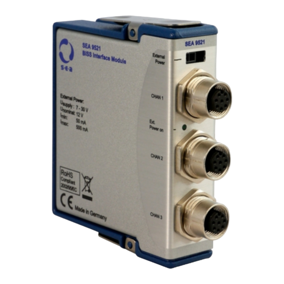
Connecting the SEA 9521 SEA 9521 provides three independent channels for BiSS-C or SSi en coders, as well as a connector for external power supply. Channel Terminals The encoder channel terminals have a M12 female con nector and accept only encoders with M12 male con... - Page 10 It is important to not switch up “+” and “-” lines. BiSS MasterOut (MO+/MO-) and SlaveIn (SLI+/SLI-) lines (as described in the BiSS-C inter face protocol) are not supported by the SEA 9521 module. If encoders with supply voltages greater than 5V are used, they have to be supplied externally.
- Page 11 The mapping between SEA 9521 connector and standard BiSS encoders can be seen in the following table: SEA 9521 BiSS Encoder Input/ BiSS Input/ Signal Signal Output Signal Output Input Data+ (D+) Output SLO+ Input Data- (D-) Output SLO- V- (0V)
-
Page 12: Double Shielding Encoder Cables
(field ground) and the inner shield t0 module ground, you should avoid connecting both shields together (causing unwanted noise). The SEA 9521 encoder connectors are connected via the SEA 9521 casing and the cRIO connector with the NI cRIO casing and earth. In many NI cRIO system, however, ground and earth are internally connected which leads to an unwanted connection between outer and inner shield. -
Page 13: External Power Supply
Fig. 3. Please check the label of the positive power cord and the ground connector. An input voltage range of 7 V DC to 30 V DC is accepted. The SEA 9521 module and any cabling is not protected against lightning strike or any over-voltage above 30 V. -
Page 14: Sleep Mode
Sleep Mode This module supports a low-power sleep mode. In sleep mode typically there is no communication with the module and the power consumption is minimized. The system thermal dissipation may decrease. Refer to the Specifications section for more information about power consumption and thermal dissipation. -
Page 15: Specifications
Specifications The following specifications are typical for the nominal temperature of 20 °C unless otherwise noted. Encoding Characteristics Number of channels 20 (with 3 encoders) Acquisition rate/ch 33 (with 1 encoder) depending on encoder Resolution type, max. 64 bit, single + multiturn Protocol BiSS-C, SSI... - Page 16 Operating voltage for the backplane Nominal Minimal Maximal Operating voltage for encoder Nominal Minimal Maximal Power consumption from chassis at 5 V: Operating current in active mode Typical Minimal Maximal Operating current in sleep mode Typical Minimal Maximal Power consumption from external connector at 12 V: Operating current in active mode Typical Minimal...
- Page 17 Power consumption from encoder at 5 V: Operating current in active mode Maximal Physical Characteristics Weight Dimensions 87 x 23 x 89 Environmental Conditions Operating Temperature °C -40 to 70 Storage Temperature °C -40 to 85 Ingress Protection IP 30 Operating Humidity 5 to 90 Shock and Vibration...
-
Page 18: Electromagentic Compatibility
50 g, 3 ms half sine, (10 shocks at 6 orientations) Tab. 1: Specifications Electromagentic Compatibility The SEA 9521 module is conform with the following European Union Dir ectives: Directive 89/336/EEC for conformity for EMC • EMC (Electromagnetic Compatibility). Standards: •... -
Page 19: Maintenance
Maintenance Only use a clean and dry towel to wipe the SEA 9521. The SEA 9521 is not water resistant and should not be operated in humid environments. The SEA 9521 does not contain components, which have to be maintained. -
Page 20: Contact And Support
Contact and Support Address: S.E.A. Datentechnik GmbH Muelheimer Strasse 7 53840 Troisdorf Germany Support channels: website: http://www.sea-gmbh.com email: techsupport@sea-gmbh.com phone: + 49 2241 12737 – 0 fax: + 49 2241 12737 – 14 Hardware Manual...
Need help?
Do you have a question about the 9521 and is the answer not in the manual?
Questions and answers