Table of Contents
Advertisement
Quick Links
Advertisement
Table of Contents

Related Manuals for Pepperl+Fuchs KFD HM 16 Series


Summary of Contents for Pepperl+Fuchs KFD HM 16 Series
- Page 1 PROCESS AUTOMATION MANUAL HART Multiplexer System KFD*-HM*-16 ISO9001...
- Page 2 HART Multiplexer System KFD*-HM*-16 With regard to the supply of products, the current issue of the following document is applicable: The General Terms of Delivery for Products and Services of the Electrical Industry, published by the Central Association of the Electrical Industry (Zentralverband Elektrotechnik und Elektroindustrie (ZVEI) e.V.) in its most recent version as well as the supplementary clause: "Expanded reservation of proprietorship"...
-
Page 3: Table Of Contents
HART Multiplexer System KFD*-HM*-16 Table of contents Introduction ..........5 Aim of the manual. - Page 4 HART Multiplexer System KFD*-HM*-16 Table of contents Configuration ..........28 PACTware introduction .
-
Page 5: Introduction
Repairs to the device must only be undertaken by specialist personnel and in compliance with the relevant regulations. We strongly recommend that repairs are undertaken by the manufacturer. No guarantee claims will be accepted by Pepperl+Fuchs GmbH resulting from Warning improper repair work. -
Page 6: Safety Instructions
All products have been developed and manufactured taking into consideration applicable European standards and regulations A Declaration of Conformity can be requested from the manufacturer. Note The manufacturer of this product, Pepperl+Fuchs GmbH in Mannheim, Germany, has a certified quality assurance system in conformity with ISO 9001. ISO9001... -
Page 7: Intended Use
Warning Reference should be made to the statement of conformity. Identification The following identification is affixed to the Multiplexer Master: Pepperl+Fuchs GmbH Lilienthalstrasse 200, 68307 Mannheim, Germany KFD2-HMM-16 PF07 CERT 1143 X II 3 G Ex nA IIC T4 Gc... -
Page 8: Installation And Commissioning
HART Multiplexer System KFD*-HM*-16 Safety instructions Installation and Commissioning 2.7.1 Installation of the warning device The device must only be installed outside potentially explosive zones. The device must not be installed in places with potentially aggressive vapors. The device must be free of voltage during installation and maintenance. The warning system must only be connected to the supply voltage after complete mounting and connection of the sensors. -
Page 9: Product Specification
• Interface converter RS 485 <> RS 232 (Telebyte Model No. 285), converter RS 485 <> RS 232, Pepperl+Fuchs order code: Telebyte Model 285M The complete product family is described in the Pepperl+Fuchs product catalogs. Please refer to the ordering instructions detailed in the catalogs. - Page 10 HART Multiplexer System KFD*-HM*-16 Product specification KFD2-HMM-16 HART RS 485 HART Termination Board FI KFD0-HMS-16 24 V DC Zone 2 24 V DC Div. 2 Power Rail Figure 3.1 Connection diagram KFD2-HMM-16 Front view 26 pin connector LED red: KFD0-HMM-16 Fault signal LED green: Power supply...
- Page 11 Suitable Fl and MB boards can be supplied by Attention Pepperl+Fuchs for this purpose. Notwithstanding the common ground connection of the analog signals from the Masters/Slaves, the galvanic isolation of the current repeaters is secured if •...
-
Page 12: Description Of The Hart Communication
HART Multiplexer System KFD*-HM*-16 Product specification Description of the HART communication The HART protocol (Highway Addressable Remote Transducer) is supported by many conventional 4 mA ... 20 mA field devices, which thus enable digital communication for configuration and servicing purposes. Many device parameters and also the measured values themselves can thus be digitally transferred to and from the device. -
Page 13: System Construction
DCS. For example, the data has to be cyclically interrogated and then stored by the system in a database. The HART Multiplex System from Pepperl+Fuchs provides the coupling between the PC and the intelligent "HART capable" field devices. All access to the field device takes place in parallel with the transfer of the 4 mA ... - Page 14 HART Multiplexer System KFD*-HM*-16 Product specification 3.3.3 Integration in the operating software (Asset Management Systems) The full potential of the HART Multiplexer System is realized through integration in modern Asset Management Systems such as PACTware (open source), SIMATIC PDM (Siemens), AMS (Fisher-Rousemount), Cornerstone (Applied System Technologies) and Valve Manager (Neles Automation).
- Page 15 HART Multiplexer System KFD*-HM*-16 Product specification 3.3.4 System construction The wiring of the single I/O components of the HART product portfolio is done via a Termination Board. Since a wide variety of Termination Boards is available, only the basic wiring options should be described here. Field devices and DCS are connected via Termination Boards in every case.
-
Page 16: Hart Multiplexer System Kfd*-Hm
HART Multiplexer System KFD*-HM*-16 Product specification Assembly integrated Multiplexer Master and Slaves are installed on Flex Interfaces, which transmits the in the DCS signals via screw terminals and system cable to the DCS. In this case the Termination Board provides the connection to the Multiplexer parallel or serial. The Termination Boards are designed especially for individual DCS. - Page 17 HART Multiplexer System KFD*-HM*-16 Product specification When using the K-System of Pepperl+Fuchs the signals can be transmitted directly Assembly integrated from the Termination Boards of the K-System to the Multiplexer Master or Slave via a in the K-System system plug.
- Page 18 HART Multiplexer System KFD*-HM*-16 Product specification 3.3.5 HART Multiplexer Slave The HART Multiplexer Slave is supplied from the HART Multiplexer Master via the 14-core flat cable. The contacting of the flat cable is provided via IDC connectors, so that the cable can be tapped at any position. By this means, the power supply and data cables are looped on from station to station.
-
Page 19: Installation
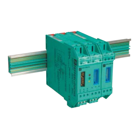
HART Multiplexer System KFD*-HM*-16 Installation Installation Mounting The K-System allows three different types of mounting: 1. wall or panel mounting 2. mounting on 35 mm DIN EN 60715 mounting rail – TH 35-7.5 (installation height 7.5 mm) – TH 35-15 (installation height 15 mm, material thickness 1.5 mm) 3. - Page 20 HART Multiplexer System KFD*-HM*-16 Installation Mounting on DIN rail with The Power Rail UPR-03-* is an insert for a DIN rail which Pepperl+Fuchs has Power Rail developed for this application. The Power Rail provides two leads for power supply of the modules and one lead for centralized error messages.
- Page 21 HART Multiplexer System KFD*-HM*-16 Installation As shown in the figure, the isolation modules are snapped onto the Universal Power Rail in a vertical downward movement. CORRECT: Device snapped on vertically. INCORRECT: Device snapped on from the side. Figure 4.4 Power supply via There are two power supply concepts for supply via the Power Rail: Power Rail •...
-
Page 22: Electrical Connection
To connect a standard PC with a RS 232 interface an interface converter RS 485 to RS 232 is required. A converter that has been tested and recommended by Pepperl+Fuchs is manufactured by Telebyte (Telebyte Model No. 285). This can be obtained from Pepperl+Fuchs under the part number "Telebyte Model 285M“. - Page 23 In accordance with the RS 485 specification up to 32 stations ("multidrop") can be connected to a up to 1200 m cable (for data rates less than 100 kBaud). Pepperl+Fuchs recommends that this length of cable is not exceeded. Even though problems seldom occur at these data rates, screened twisted two-wire cabling should be used.
-
Page 24: Commissioning
HART Multiplexer System KFD*-HM*-16 Commissioning Commissioning Commissioning check list The commissioning of the Multiplexer Master is summarized in the following check list. You should follow the list through in sequence, actions that have already been carried out can be skipped. The steps required for commissioning the Multiplexer refer to the section in which the respective procedure is described in detail. -
Page 25: Fdt Framework Pactware Tm
HART Multiplexer System KFD*-HM*-16 Commissioning FDT framework PACTware PACTware is the first open source Process Automation Configuration Tool with an open FDT interface (Field Device Tool). For the first time this enables all field buses and field devices in a system, independent of the manufacturer, to be configured and assigned parameters using a single engineering tool. - Page 26 HART Multiplexer System KFD*-HM*-16 Commissioning To accept the values set on the DIP switches, the device must be isolated briefly from power supply. Note Condition on delivery Meaning switch Setting Manufacturer test de- activated baud rate 9600 Baud RS 485 address 0 The address 0 is set on the device when delivered.
- Page 27 HART Multiplexer System KFD*-HM*-16 Commissioning 5.4.5 Device parameter, parameterization For the identification and programming of the Multiplexer Master, this contains - as do other HART field devices - specific parameters that are in the non-volatile memory. The following list shows these parameters and how the programming must be carried out.
-
Page 28: Configuration
PACTware is Pepperl+Fuchs latest generation of configuration software that makes it easy to program Pepperl+Fuchs’s equipment. In addition to becoming single configuration tool, PACTware interfaces with HART capable field instruments as well as bus systems such as PROFIBUS, Modbus and ControlNet. -
Page 29: Connection With The Device
HART Multiplexer System KFD*-HM*-16 Configuration Installing the software components The installation of the software components is described in the "PACTware Installation Instructions" manual. Please observe the sequence of the installation steps and the instructions in the installation instructions. Install Microsoft .NET Framework. - Page 30 HART Multiplexer System KFD*-HM*-16 Configuration The main window is divided into the project window and the edit window. Project window The current project tree for your system is constructed in the project window by adding the various components. Three buttons for adding, removing and editing components appear at the bottom of the window.
-
Page 31: Adding The Communications Dtm
HART Multiplexer System KFD*-HM*-16 Configuration Adding the Communications DTM In a PACTware project the HART Multiplexer KFD2-HMM-16 can be addressed by Communications DTM HART Communication only. Please refer to the "PACTware Process Automation Configuration Tool" manual to read how to create and edit a project. - Page 32 HART Multiplexer System KFD*-HM*-16 Configuration Setting the parameters In the project window, use the mouse to double-click on the Communications DTM HART Communication. The Parameter window is indicated. Use the OK button to close the Parameter window. The following parameters are adjustable: •...
-
Page 33: Adding The Hart Multiplexer
HART Multiplexer System KFD*-HM*-16 Configuration Adding the HART Multiplexer In the Communications DTM, the function Additional functions > Scan list can be used to scan the connected HART Multiplexer. Update Scan list Click in the project window with right mouse button on HART Communication. ... -
Page 34: Setting The Parameters Of The Hart Multiplexers
HART Multiplexer System KFD*-HM*-16 Configuration Setting the parameters of the HART Multiplexers 6.6.1 Parameterizing parameters off-line Adjust the parameter of the Master Double-Click in the project window with mouse button on Multiplexer. Open the Master menu. The Master window is indicated. The following parameters are adjustable: •... - Page 35 HART Multiplexer System KFD*-HM*-16 Configuration 6.6.2 Read-out the data Use Load from device to read the parameters of the Multiplexer in order to establish a connection. Is no standard online/off-line view as usually used for FDT DTMs. Note Figure 6.6 Read-out the Data...
- Page 36 HART Multiplexer System KFD*-HM*-16 Configuration Parameterizing of the scan function Double-Click in the project window with mouse button on Multiplexer. Open the Scan menu. The Scan window is indicated. The scan function is used by the HART Multiplexer to cyclically retrieve data from the connected field devices which are saved in the memory.
- Page 37 HART Multiplexer System KFD*-HM*-16 Configuration Parameterizing of the communication Double-Click in the project window with mouse button on Multiplexer. Open the Communication menu. The Communication window is indicated. The Communication menu is used to set the communication parameters between the HART Multiplexer and the field device.
- Page 38 HART Multiplexer System KFD*-HM*-16 Configuration Message menu Double-Click in the project window with mouse button on Multiplexer. Open the Message menu. The Message window is indicated. The Message menu can be used to give the HART Multiplexer an identification name.
- Page 39 HART Multiplexer System KFD*-HM*-16 Configuration Device info menu Double-Click in the project window with mouse button on Multiplexer. Open the Device info menu. The Device info window is indicated. The Device info menu renders general information on the device: •...
- Page 40 HART Multiplexer System KFD*-HM*-16 Configuration Active modules menu Select the Multiplexer Master in the project window. Open the Active modules menu via Device > Additional functions > Active modules. The Active modules window is indicated. Select the active modules for each Multiplexer. As a standard, only the Master is activated;...
- Page 41 HART Multiplexer System KFD*-HM*-16 Configuration 6.6.3 HART Scan Use a HART Scan to read in the entire project structure connected to the serial interface: • HART Multiplexer Master • HART Multiplexer Slaves • Field devices Start HART Scan function Select the Multiplexer Master in the project window. ...
- Page 42 HART Multiplexer System KFD*-HM*-16 Configuration Before start the HART Scan select the desired options: Setting Scan functions Open the Scan parameters via Settings folder. The Settings window is indicated. The following parameters are adjustable: • Start Scanning for active slaves: This option is used to determine whether a search for connected Slaves is to be run.
- Page 43 HART Multiplexer System KFD*-HM*-16 Configuration Setting of further Scan functions Open further Scan functions via the Other folder. The Other window is indicated. For some field devices (e. g. from VEGA) it may be necessary to render available additional information by means of an XML file.
- Page 44 HART Multiplexer System KFD*-HM*-16 Configuration The HART Scan queries the allocation table of the HART Multiplexer. The allocation table contains the loop number and the long frame address of the device connected to this loop. This is built up during the power on of the HART Multiplexer. If after the power on of the HART Multiplexer another device is connected, the allocation table can be built by means of the Rebuild loops option.
- Page 45 HART Multiplexer System KFD*-HM*-16 Configuration The HART Scan is started by means of the Start button in the right lower corner. Now the topology of the connected devices is built by reading in the field devices connected to these devices by means of HART Multiplexer and HART Slaves. •...
- Page 46 HART Multiplexer System KFD*-HM*-16 Configuration After the scan, the right table will show the following information on the DTM suggested: • Manufacturer ID • Device type • Sub Device Type • Name of the DTMs • Manufacturer of the DTMs •...
- Page 47 HART Multiplexer System KFD*-HM*-16 Configuration Read-out of parameters Read-out the device parameters via Project > Upload. Figure 6.18 Read-out of parameters The project is now complete and contains all required information.
- Page 48 HART Multiplexer System KFD*-HM*-16 Configuration If other Slaves are added later, the already existing Slaves can be excluded from the scan. Use the right mouse button to click on the Slave to be excluded. Activate the Exclude option. Figure 6.19 Exclude existing Slaves from the scan...
-
Page 49: Operation
HART Multiplexer System KFD*-HM*-16 Operation Operation Device functions The software functions described in this section are normally integrated into the operating software for the servicing station, i. e. the functions are not generally (de-)activated via the described HART commands. In contrast the operating software uses functions (menu commands) to control these procedures. - Page 50 HART Multiplexer System KFD*-HM*-16 Operation • Extended messages and messages in the Burst Mode are recognized and used, but not generated by the Multiplexer itself. • An answer buffer is available for a delayed message response. This can be used to intermediately store a message, the command for which requires a long execution time.
- Page 51 HART Multiplexer System KFD*-HM*-16 Operation 7.1.9 All the functions at a glance The following list gives all the functions once again at a glance: • 16 channels, extendable to 256 channels by the connection of up to 15 KFD0-HMS-16 Slaves •...
-
Page 52: Diagnosis And Fault Elimination
Fault in device hardware Send device to Pepperl+Fuchs for (CPU, ROM) repair. • Fault in device hardware • Send device to Pepperl+Fuchs for (CPU, RAM) repair. • Device parameter assignment • Parameterize device again. If this is incorrect (parameter Loop... - Page 53 HART Multiplexer System KFD*-HM*-16 Diagnosis and fault elimination 8.3.2 Structure of the first byte If Bit 7 is set (1), the first status byte contains a summary of the communication errors. This information is coded bit by bit. If Bit 7 is cleared (0), the first status byte contains a summary of the command responses.
- Page 54 HART Multiplexer System KFD*-HM*-16 Diagnosis and fault elimination The following response codes can occur on the Multiplexer: Description Meaning Can occur with Code commands ... Invalid selection The selected code/index is not permissible. 147, 149, 151, 153 The parameter value was too 59, 129, 155 large The parameter value was too...
- Page 55 HART Multiplexer System KFD*-HM*-16 Diagnosis and fault elimination 8.3.3 Device status (structure of the second byte) If a communication error is indicated in the first byte (Bit 7 = 1), the second byte described here has no significance (always 0). In the other case, it contains the status of the field device in full, i.e.
-
Page 56: Extended Device Status
OR logic operation on all detected hardware faults in the current loops. Check the transmitter and its cabling, then execute REBUILD. ROM error Send device to Pepperl+Fuchs for repair. EEPROM error Send device to Pepperl+Fuchs for repair. 4 ... 0 reserved Reserved. -
Page 57: Appendix
HART Multiplexer System KFD*-HM*-16 Appendix Appendix Supported commands The following tables show the HART commands supported by the Multiplexer, ordered by three groups (see also section 3.2): • Universal commands, • Common-practice commands and • Device specific commands. The read commands are caracterized by and the write commands by . The Universal and Common-practice commands are described in detail in /1/. - Page 58 HART Multiplexer System KFD*-HM*-16 Appendix 9.1.2 Common-practice commands Command Action Meaning Reset "Configuration changed" flag. Reset the "Configuration changed" response code, see section 8.3.3. Perform device self test. Initiates the self test function in the device (as during power up);...
- Page 59 HART Multiplexer System KFD*-HM*-16 Appendix Command Action Meaning Read dynamic data of up to 7 For the given long frame addresses the function returns the transmitters. following transmitter data: • The selected SCAN command • Long frame address • HART data Read SCAN status of up to 31 For the given long frame addresses, this command returns transmitters.
-
Page 60: Terminal Assignment Of The 26 Pin Connector With Analog Hart Signals
HART Multiplexer System KFD*-HM*-16 Appendix Command Action Meaning Read Multiplexer table (module This command returns the Multiplexer table (see 157). table) (16 Multiplexers). Write Multiplexer table (module This is to select which of the Multiplexers (Master and 15 table) (16 Multiplexers). -
Page 61: Literature
HART Multiplexer System KFD*-HM*-16 Appendix Literature HART Communication Foundation: HART – SMART Communications Protocol Specification HCF SPEC-11, Revision 5.9 www.hartcomm.org HART Communication Foundation: HART Application Guide HCF LIT 34 www.hartcomm.org Romilly Bowden, Fisher-Rosemount: HART- A technical Overview, August 1997 Fisher-Rosemount... -
Page 62: Glossary
HART Multiplexer System KFD*-HM*-16 Appendix Glossary Address In communications technology, the address of a device is used to identify that device, so that messages can be delivered correctly. HART uses two forms of addressing: a polling address in the range 0 to 15, and a unique identifier (long frame format address) of 38 bits. The polling address 0 is reserved for 4 mA ... - Page 63 HART Multiplexer System KFD*-HM*-16 Appendix Secondary variable Additional value (measured in the process) of a field device (up to four additional values are supported by HART). This variable can only be read by HART command 3. Slave A device (e. g. transmitter or valve) in a Master-Slave system that receives commands from a ...
- Page 64 PROCESS AUTOMATION – PROTECTING YOUR PROCESS Worldwide Headquarters Pepperl+Fuchs GmbH 68307 Mannheim · Germany Tel. +49 621 776-0 E-mail: info@de.pepperl-fuchs.com For the Pepperl+Fuchs representative closest to you check www.pepperl-fuchs.com/contact www.pepperl-fuchs.com Subject to modifications DOCT-0120D Copyright PEPPERL+FUCHS • Printed in Germany 06/2014...
Need help?
Do you have a question about the KFD HM 16 Series and is the answer not in the manual?
Questions and answers