Table of Contents
Advertisement
Quick Links
OPŠTA UPOZORENJA
• Nakon uklonjenog pakovanja uveriti se u kompletnost isporuke, i u slučaju nedostataka,
obratiti se prodavcu koji je prodao kotao
• Kotao mora biti upotrebljen isključivo za namenu koju je predvideo proizvo ač.
Isključuje se bilo kakva odgovornost od strane proizvo ača za štetu uzrokovanu
osobama, životinjama ili stvarima, u slučaju grešaka pri montaži, regulaciji, održavanju
ili nepravilnom korišćenju.
• U slučaju curenje vode isključiti ure aj sa električnog napajanja, zatvoriti napajanje
vodom i obavestiti ovlašćeni servisi ili ovlašćenog montera.
• Ovo uputstvo je sastavni deo ure aja i mora se čuvati sa pažnjom i mora UVEK pratiti
ure aj i u slučaju promene vlasnika ili korisnika ili u slučaju priključenja na drugu
instalaciju. U slučaju oštećenja ili nestanka tražiti novi primerak od ovlašćenog prodavca.
INSTRUKCIJE/ INSTRUCTION MANUEL
Montaža,korišćenje i održavanje kotla/ Assebly,use and maintenance of heating boiler
Kotao na
BIOMASU/
Heating boiler
BIOMASS
OPERATED
SERIJE
BIOmax/
SERIES
BIOmax
Advertisement
Table of Contents

Related Manuals for Radijator BIOmax Series


Summary of Contents for Radijator BIOmax Series
- Page 1 SERIJE Kotao na BIOmax/ BIOMASU/ SERIES Heating boiler BIOmax BIOMASS OPERATED OPŠTA UPOZORENJA • Nakon uklonjenog pakovanja uveriti se u kompletnost isporuke, i u slučaju nedostataka, obratiti se prodavcu koji je prodao kotao • Kotao mora biti upotrebljen isključivo za namenu koju je predvideo proizvo ač. Isključuje se bilo kakva odgovornost od strane proizvo ača za štetu uzrokovanu osobama, životinjama ili stvarima, u slučaju grešaka pri montaži, regulaciji, održavanju ili nepravilnom korišćenju.
- Page 2 Sadržaj: 1. Važna upozorenja; 2. Opis kotla; 3. Montaža; 3.1 Opšta upozorenja; 3.2 Mere i uredjaji bezbednosti kod kotlova BIOmax; 3.3 Kotlarnica; 3.4 Priključenje na dimnjak; 4. Presek BIOmax kotla sa opisom elemenata; 5. Šema veze automatike; 6. Tabela sa tehničkim podacima; 7.
- Page 3 1.Važna upozorenja OPŠTA UPOZORENJA • Nakon uklonjenog pakovanja uveriti se u kompletnost isporuke, i u slučaju nedostataka, obratiti se prodavcu koji je prodao kotao • Kotao mora biti upotrebljen isključivo za namenu koju je predvideo proizvo ač. Isključuje se bilo kakva odgovornost od strane proizvo ača za štetu uzrokovanu osobama, životinjama ili stvarima, u slučaju grešaka pri montaži, regulaciji, održavanju ili nepravilnom korišćenju.
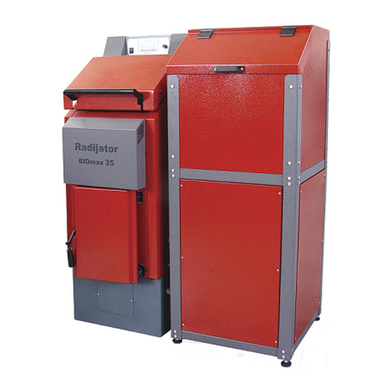
- Page 4 2.Opis kotla Kotao serije BIOmax je razvijen sa ciljem da RADIJATOR INŽENJERING ponudi tržištu kotao koji je po svojim mehaničkim i termičkim osobinama izrazito namenjen biomasi kao gorivu. Koristeći uopšteni pojam „BIOMASA“ naravno da se pre svega misli na pelet,ali treba istaći i mogućnost loženja sa košticama voća i to pre svega višnja,trešnja.Ukoliko korisnik želi da...
- Page 5 Stepen korisnosti na pelet je preko 90%. Pri normalnim režimima temperatura dimnih gasova na izlazu je oko 130 ̊ C ,a pri maksimalnim režimima je ispod 150 ̊ C . Ove vrednosti mogu u svakom trenutku da se očitaju na displeju.Tokom rada dolazi do stvaranja naslaga gareži i pepela na izmenjivačkom delu kotla i to značajno utiče na slabiju izmenu i porast temperature dimnih gasova.Ako se kotao ne čisti duže vreme moguć...
- Page 6 Slika2. Prikaz demontažnih celina kotla 1. Telo kotla 2. Ložište 3. Pepeljara 4. Pužni transporter-dozer 5. Silos...
- Page 7 3.Montaža 3.1 Opšta upozorenja Kotao se isporučuje sa spoljnom oblogom koja sadrži izolaciju debljine 30mm Položaj silosa i mehanizma za transport peleta je standardno fabrički desni u odnosu na kotao. Moguće je naručiti da se u fabrici sklopi i leva varijanta.Tako e,ako je potrebno lako je promenu izvršiti i na terenu jer je silos i ceo mehanizam dozatora demontažan u odnosu na kotao.Elektro priključci su konektorskog tipa tako da za njihovo rastavljanje i ponovno sastavljanje nije potrebno osoblje specijalizovane elektro struke.
- Page 8 Kotao je sa 3 ventilatora ,automatikom kao i keramičkim grejačima za potpalu i svi ovi uredjaji koriste napajanje 230V,tako da nepravilno instaliranje i neoprezno rukovanje mogu da ugroze ljudski život strujnim udarom. Kotao na čvrsto gorivo i prinudnom promajom treba instalirati prema važećim normama i zakonskim propisima.Svaka izmena ili na mehaničkoj konstrukciji ili na električnoj instalaciji smatraće se narušavanjem garancijiskih uslova i dovešće do njenog narušavanja.
- Page 9 3.2 Mere i uredjaji bezbednosti kod kotlova BIOmax; Za bezbedan rad kotla potrebno je ugraditi i održavati ih ispravnim sledeće elemente: - Ventil sigurnosti na pritisak (slika 4) Slika 4 Slika 5 Ventil sigurnosti na pritisak mora biti nazivnog prečnika 1/2 cola baždaren na maksimalno 3 bara.
- Page 10 - Ventil termičkog osiguranja oticanjem (slika 6) Slika 6 Ovaj sigurnosni element ima tako e ulogu ograničivača temperature.U daljem tekstu biće označen sa skraćenicom VTO. U nekim ekstremno opasnim situacijama prelaz vode u vodenu paru je takav da ventili sigurnosti za pritisak nisu dovoljni da obezbede sigurnost hidrauličkog sistema. Iz ovog razloga je obavezna ugradnja VTO.U zavisnosti od zakonskih regulativa zemalja u kojima se kotao montira, VTO je potrebno ugraditi samo za snage veće od odre enih ili za svaku snagu kotla obavezno ugraditi VTO.
- Page 11 Slika 7.Prikaz postavljanja sigurnosnih elemenata Termostati u automatici kotla - U samoj automatici koja vodi proces sagorevanja i utiče na rad dva kruga grejanja postoje dva termostata.Oba su slične konstrukcije kao termostat prikazan na slici 8. i imaju i sigurnosne funkcije kao limitatori temp. vode u kotlu.Zbog sigurnosne uloge u funkcionisanju kotla oba termostata imaju nezavisne sonde za merenje temperature vode.
- Page 12 3.2 Kotlarnica Kotlarnica mora biti obezbedjena od smrzavanja. Podloga za kotao u kotlarnici mora biti od nezapaljivog materijala.Preporučene vrednosti udaljenosti sve četri strane kotla u odnosu na zidove kotlarnice ili neka druga kruta tela (akomulacioni bojler itd.)prikazane su na slici 9.Ove vrednosti udaljenosti omogućavaju siguran pristup prilikom loženja,dovoljan prostor za čišćenje i nesmetan pristup ventilatoru i ventilu za punjenje i pražnjenje.
- Page 13 Ukupna površina ovih otvora je minimalno 150cm² za snage do 50kW a za snagu preko 50kW površina mora biti veća za jos 2cm² po kilovatu. ∑ A=150cm²+ ∑ Q = moguće snage preko 50kW. × − Nedostatak dovoljne ventilacije u kotlarnici može da uzrokuje više problema u radu kotla.Glavni problem je nemogućnost postizanja visokih temperature izlažne vode tj.ne postizanje maksimalne snage što dovodi do kondezovanja u kotlu.
- Page 14 3.3 Priključenje na dimnjak Kotao Biomax radi sa prinudnom promajom i to pod dejstvom dva ventilatora, ali ipak treba ispoštovati pravila za odabir dimnjaka kao da se radi o kotlu sa blagim potpritiskom u ložištu na neko drugo gorivo,kao na lož ulje na primer.Empirijski,na osnovu našeg iskustva poprečni presek dimnjaka treba da bude barem jednak prečniku dimnjače kotla tj.
- Page 15 od 12 i ako je ugao krova veci od 12 .Za ugao manji od 12 visine dimnjaka iznad krova je 1m a za ugao veci od 12 treba pogledati skicu Ukoliko mislite da je dimnjak prejak i da isuviše hladnog vazduha prolazi kroz kotao,na izlazu iz kotla postoji klapna kojom može da se smanji protok izduvnih gasova.
- Page 16 4. Presek TKAN kotla sa opisom elemenata slika 11. Presek kotla TKAN BIOmax...
- Page 17 1. Vrata za potpalu i čišćenje 2. Vrata za loženje (prilikom loženja kotla na drvo) 3. Poklopac otvora za čišćenje izmenjivačkih cevi 4. Ložište (za PELET) 5. Liveni demontažni segmenti 6. Donji pužni transporter 7. Ćelijasti transporter – VALVOLA 8. Gornji pužni transporter 9.
- Page 18 5. Šema vezivanja automatike...
- Page 19 Sve linije koje su prikazane isprekidano na šemi spoljnih priključenja su provodnici koje je potrebno da instalira tehničko lice prilikom priključenja spoljnih ure aja na automatiku kotla. Sva priključenja dodatnih ure aja tehničko lice obavlja preko dva konektora koja se nalaze na zadnjem delu kotla.Jedan konektor je tropolni a jedan je sedmopolni.
- Page 20 6. Tabela sa tehničkim podacima D1-priključci za toplu Tip kotla BIOmax23 BIOmax35 vodu iz kotla mere Snaga 17-23 20-35 D2- priključci za hladnu Radni pritisak vodu iz kotla Probni pritisak Zapremina vode u kotlu L-cca D3- priključak za punjenje Masa kotla Max.temp.potisnog voda i pražnjenje kotla Min.temp.povratnog voda...
- Page 21 7. Hidraulična šema...
- Page 22 1. Toplovodni kotao na pelet BIOmax 2. Cirkulaciona pumpa 3. Nepovratni ventil 4. Zaporna slavina 5. Hvatač nečistoće 6. Zatvorena ekspanziona posuda 7. Akumulator (pufer) 8. Trokraki mešni ventil 9. Ventil sigurnosti 10. Slavina za punjenje i pražnjenje 11. Termometar 12.
- Page 23 8. Start rada kotla Prvo puštanje kotla u rad obavlja tehničko lice koje ima sertifikat izdat od strane Radijator inženjeringa. Na taj način to lice je ovlašćeno da prijavi servisnoj službi u samoj fabrici vreme kada je kotao počeo da radi i u kakvom je stanju kotao bio prilikom prvog paljenja.
- Page 24 8.1 Displej automatike Komandni panel sačinjavaju: Glavni prekidač, dugme sigurnosnog termostata, displej,grupa komandnih tastera (dugmića), grupa svetlosnih dioda pokazivača Sledeća slika je prikaz kontrolnog panela. 8.1.1 Komandni tasteri U DONJEM DESNOM UGLU SVAKOG KOMANDNOG TASTERA OZNAČEN JE BROJ. - UKLJ.-ISKLJ.PELET/+KOMANDNO DUGME 4 : Uključuje rad sistema na pelet kao gorivo kada se drži neprekidno 5 sekundi.
- Page 25 - ESC/Menu KOMANDNO DUGME 1 : Ovim tasterom se ulazi/izlazi iz Menija (Menu). Ukoliko menjate podešavanja i pritisnete ovo dugme, promene u podešavanjima neće biti sačuvane. NAPOMENA: U režimu Isključen (OFF) ili u režimu Gašenje možete resetovati prikaz Alarma pritiskom na tastere + ili -, ali ako je uzrok alarma i dalje prisutan alarm će se ponovo uključiti 8.1.2 Svetleće diode 1.
- Page 26 Prikaz Opis Prikaz Opis Otvoren je priključak sigurnosnog termostata – tastera za ručno Slučajno gašenje resetovanje Sigurnosni režim Očitavanje sonde van opsega Ne uspelo paljenje NAPOMENA: - Uključivanje Termoleguratora putem Glavnog prekidača, Kod proizvoda i Verzija firmera su prikazane u dužini od 2 sekunde. Prikaz Opis Prikaz...
- Page 27 slika 13. Položaj klapne ventilatora slika 14. Položaj max. otvorene klapne vent. • Utičnicu na zadnjoj strani kotla spojiti sa glavnim mrežnim napajanjem. • Sipati manju količinu peleta u silos i zatvoriti ga. • U ovoj fazi potrebno je ubaciti pelet u komoru za sagorevanje i to radom transportnog mehanizma za pelet(pellet feeding system).Na taj način postižemo kontinualno raspore en pelet od komore za sagorevanje pa do silosa.Do pokretanja mehanizma za pelet može doći samo u fazi rada kada na displeju piše ,,OFF,,.Tada pritiskom na...
- Page 28 donjem delu ovog dugmeta prikazan je i simbol za rastresit materijal,odnosno pelet. U trenutku kada kotao krene u potpalu na displeju piše Chc i u ovih nekoliko sekundi radi samo ventilator.Za vreme ove faze automatika proverava da li su svi ure aji neophodni za rad zaista i priključeni.
- Page 29 • Prilikom startovanja rada kotla (pritiskom na GLAVNI PREKIDAČ) ,potrebno je prebaciti automatiku na režim rada DRVO. Potrebno je najpre isključiti režim rada pelet(ako je uključen) tako što će te držati komandno dugme 4(simbol +,više od 3sekunde),na displeju će vam se pojaviti oznaka Spe .Tada treba otpustiti taster.Zatim pritisnuti komandno dugme 3(sibol -,više od 3sekunde),na displeju će vam se pojaviti oznaka Chc,kao i blinkanje signalne lampice iznad komandnog dugmeta 3.
- Page 30 Ako lampica 1 pored samog simbola za puž blinka pritisnuti promeniti vrednosti doziranja puža na željenu I ponovo pritisnuti blinka puž 8.3.4 PROMENA JAČINE VENTILATORA U RADNOM REŽIMU. blinka puž blinka vent. 8.3.5 PROMENA ZADATE TEMPERATURE VODE U KOTLU. blinka puž blinka vent.
- Page 31 8.3.7 KAKO OČITATI TEMPERATURU DIMOVODNIH GASOVA. fumi 8.3.8 ULAZAK U SKRIVENI MENI. Pritisnuti i držati,odmah zatim pritisnuti i držati oba dugmeta 5 sekundi. Odmah po ulasku u skriveni MENI na displeju piše CL 00. To je prvi parametar. 8.4 Greške prilikom startovanja kotla Sve moguće greške u početnoj fazi rada tj.
- Page 32 Postupak za rešavanje PROBLEMA 2 – Pričvrstiti crevo za vazduh i na kućište grejača i na cev kanala za vazduh Moguć uzrok 3 PROBLEM 3 – Prostor izme u grejača i cevnog kućišta u kome je zavijen grejač je zapušen sa katranom i pepelom tako da nema prodora vazduha. Postupak za rešavanje PROBLEMA 3 –...
- Page 33 Grupa II Moguć uzrok 1. PROBLEM 1 – Zatvorena je klapna u kotlu kojom se rukuje sa ručicom koja je na bočnoj strani.Pojavljuje se mnogo dima a dimni gasovi nemaju dovoljno brz porast tako da kotao ide u gašenje. Postupak za rešavanje PROBLEMA 1 – Otvoriti klapnu,tj gurnuti ručicu ka dimnjaku Moguć...
- Page 34 Moguć uzrok 6 PROBLEM 6 – Kotao je prošao i fazu stabilizacije ali ide u modulaciju,na displeju piše Nod.Ako se provere dimni gasovi u tom se trenutku zapaža da su previsoki. Postupak za rešavanje PROBLEMA 6 – Proveriti da li je klapna unutar kotla u položaju ,,otvoreno’’.Zatvoriti klapnu tj.
- Page 35 Previše nesagorelog peleta pri kretanju kotla u rad. Otklanjanje uzroka greške : 1. Povećati parametar t04 2. Smanjiti parametar t05 3. Smanjiti snagu ventilatora za primarno sagorevanje u fazi održavanja plamena parametar Uc09. 8.5 Održavanje kotla BIOmax Kotao BIOmax zahteva svakodnevno i periodično čišćenje. •...
- Page 36 Na ovaj način obavezno konzervirati kotao na kraju grejne sezone. U toj situaciji zatvoriti i sve otvore na kotlu da ne dodje do cirkulacije vazduha kroz kotao jer i tako može doći do pojave vlage u kotlu. Održavanje kotla je jedan od najbitni faktora za dužinu radnog veka kotla.
-
Page 37: Table Of Contents
CONTENTS: 1. Important warning 2. Description of the boiler 3. Assembly 3.1 General warnings 3.2 Measures and safety devices for boilers; 3.3 Boiler room 3.4 Connection to the chimney 4. Cross-section of TKAN Boiler witha description of the boiler elements 5. -
Page 38: Important Warning
1. Important warnings GENERAL WARNINGS After the removing of the package check for the completeness of the delivery, in the case • of defects, please contact the dealer who sold the boiler The boiler must be used solely for the purpose envisaged by the manufacturer. Any •... - Page 39 2.Opis kotla Boiler TKAN is developed as the Company RADIJATOR ENGINEERING might offer to the market the boiler , which by its mechanical and thermal properties is specially intended for biomass as fuel Using the general term "BIOMASS" of course, it is primarily meant and considered - the pellet, but it should be noted and the possibility of firing the seeds of fruit (cherries, blackcherries...).
- Page 40 thermal safety as well as the flap for fire initiation. All parts of the water portion of boiler are made of seamless pipe ST 35.4 quality and boiler plate thickness of 4 mm or more, depending on the power of boiler. Sheets are of the quality of the Standard 1.0425 EU i.e. Standard P265GH EUII Figure1.
- Page 41 Figure2. Parts of boiler Discription: 1. Body of boiler; 2. Combustion chamber; 3. Feeder; 4. Silos; 5. Ashtray.
- Page 42 3. Assembly 3.1 General warnings The boiler is supplied with an external coating containing insulation,30mm thick. The position of the silo and the mechanism of transport of pellets is a standard factory right in relation to the boiler.It is possible to order the factory assembled and left variant. Also, if you need to easily make changes in the field because the silos and the whole mechanism disassemble dosing in relation to the boiler.
- Page 43 Solid fuel boiler and forced draft should be installed according to valid standards and legal regulations. Any mechanical or electrical change in the design or installation shall be deemed a violation of guarantee conditions and will lead to its distortion. When transporting or irresponsible manipulation of the spare parts, if there is a shock in the circuit that is used for kindling likely the damage of the ceramic heater.
-
Page 44: Measures And Safety Devices For Boilers
3.2 Measures and safety devices for boilers BIOmax For safe operation of boiler it is necessary to assemble and maintain the following elements in working condition: - Pressure Safety valve (Figure 4) Figure 4 Figure 5 • Pressure safety valve must be of nominal diameter of 1/2 inch calibrated to a maximum of 3 bars. - Page 45 accordance with the law of every country in which the boiler is assembled. Always keep the written documentation of the last calibration data for the safety valve. • On the return line assemble at least another pressure safety valve. - The valve of thermal safety by swelling (Figure 6) Figure 6 This safety element also has a role of a limitator of temperature.
- Page 46 As stated above one end of the VTO is for the mounting on the exchanger of the boiler, and the other is supplied with cold water under pressure. It is particularly important that the water flow is unobstructed even when the electricity is switched off. If it is impossible to provide the inflow of cold sanitary water at the time of electricity switch off , the boiler must be connected onto the open system.
- Page 47 It is very important to connect the pump for heating through automation for safety reasons. When the temperature of water in the boiler reaches the critical value of 95 degrees the fan stops working, but the pump is necessarily switched on to exchange the heat of water through radiators.
-
Page 48: Boiler Room
3.3 Boiler room Boiler room must be secured against freezing The support surface of the boiler in the boiler room must be of non-combustible material. Recommended distance of all four sides of the boiler in relation to the boiler walls or other solid body (water heater, etc.. - Page 49 Total space of this openings is minimum 150cm² fro the boilers of the power of 50kW and for the power over 50kW the space must be larger for another 2cm² per 1kW ∑ A=150cm²+ ∑ Q = possible power of over 50kW. ×...
- Page 50 3.3 Priključenje na dimnjak Boiler Biomax works with forced draft and is under the influence of two fans, but we also need to respect the rules for the selection of the chimney as it is a boiler with mild potpritiskom in fireplace to another fuel, such as fuel oil, for example.
- Page 51 If you think that the chimney is too strong and too much cold air passes through the boiler, at the exit of the boiler there is a valve which can reduce the flow of exhaust gases. The chimney should be cleaned regularly or at least once a year. If the chimney is not of proper height, cross section, or if it is not enough clean as possible, then the complications in the work of boiler are possible.
- Page 52 Cross-section of BIOmax Boiler with a description of the boiler elements Figure 11. Cross-section of BIOmax...
- Page 53 1. Lower door for firewood and cleaning; 2. Upper door for wood loading; 3. Cover for cleaning; 4. Combustion pellets; 5. Cost iron elemetnts; 6. Lower screw conveyor; 7. Rotation safety element; 8. Upper screw conveyor; 9. Grattings (cast iron grattings); 10.
-
Page 54: Schematic Connection Of Automation
5. Schematic connection of automation... - Page 55 All lines that are displayed in the intermittent form in the diagram of external connections are the conductors which should be installed by the technician when connecting the external devices onto the automation system of the boiler. All the connections of the additional devices are performed by the technician through three connectors located at the rear of the boiler.
- Page 56 6. Table of technical data Type of boiler BIOmax23 BIOmax35 D1-hot water Power 17-23 20-35 Working pressure D2- cold water Test pressure Volume of water in boiler L-cca D3- cold water inlet/outlet Weight of boiler Max.temp.hot water D4- Accessory for Min.temp.cold water pressure safety valve.
-
Page 57: Hydraulic Scheme
7. Hydraulic scheme... - Page 58 1. Boiler BIOmax; 2. Pump; 3. Non-return valve; 4. Valve; 5. The catcher dirt; 6. Expansive vessel; 7. Puffer; 8. Mixing valve; 9. Safety group; 10. Valve for inlet/outlet cold water; 11. Thermometer 12. Manometar 13. Over heating temperature safety valve; 14.
- Page 59 8. Start rada kotla Prvo puštanje kotla u rad obavlja tehničko lice koje ima sertifikat izdat od strane Radijator inženjeringa. Na taj način to lice je ovlašćeno da prijavi servisnoj službi u samoj fabrici vreme kada je kotao počeo da radi i u kakvom je stanju kotao bio prilikom prvog paljenja.
-
Page 60: Control Panel
8.1 Control panel Control panel consisting of: The main switch, safety thermostat button, the display, the group command buttons (buttons), a group of light-emitting diode pointer The picture below is the image of the Control Panel 8.1.1 Buttons - ON-OFF Pellet/ +: If pushed for five seconds it switches on the system goes in ON/OFF Pellet If pushed in Menu it increments a parameter’s value. - Page 61 In OFF or Extinguishing state you can reset an Alarm visualization by pushing (+) or (-) button, but if the alarm were still there you would visualize it again 8.1.2 Led 1. Led Auger : It is ON when the Auger Output is ON. 2.
- Page 62 NOTE: - Switching on the control board by the General Switch, Product Code and Firmware Version are displayed for 2 seconds. Display Discription Display Discription Product Code Program Version 8.2 Operation start of boiler on biomass • Boiler connected to Hydraulic system. •...
- Page 63 slika 13. Položaj klapne ventilatora slika 14. Položaj max. otvorene klapne vent. • Power outlet on the back boiler connected to the main power network. • Infuse a small amount of pellets in the silos and close it. • At this stage it is necessary to insert the pellets into the combustion chamber by means of the work of the transport mechanism for the pellet (pellet feeding system).
- Page 64 performed by pressing and holding the command button 4 for more than 3 seconds.On the lower part of this button there is the displayed symbol for the loose material or pellets. At a time when the boiler goes on the with the start of ignition, on the display there is the mark –written as Chc, for the few seconds only the fan is working During this phase of the automatic system checks whether all devices necessary for the operation are actually connected.
-
Page 65: Start Of Work Of Boiler By Solid Fuel
8.3 Start of work of boiler by solid fuel If the user wants the operation of the Solid fuel boiler the following steps should be taken: • If the boiler had never been used on the pellets, but it is used for the first time using solid fuel, then it is necessary to pull in a small amount of pellets into the chamber. -
Page 66: Short Manual For Automatic Control
8.3 Short manual for automatic control 8.3.1 Re-LOADING FIREBOX WITH PELLETS, PREPARATION OF STARTING • Infuse pellets in a silos. • The main display must write OFF • Push the button and keep . As long as we keep working conveyor button and the display says LOAD PELET. - Page 67 bliking auger 8.3.4 Change in volume fan operating mode. bliking auger bliking fan 8.3.5 Change the set temperature in the boiler. bliking auger bliking fan bliking pump bliking temp.water 8.3.6 CHANGING THE WAY MANUEL OR AUTOMATIC IGNITION. bliking auger bliking fan bliking pump bliking temp.water bliking WAY of ignition...
-
Page 68: Mistakes During Ignition And Start Of The Boiler
8.3.8 Entry into the hidden menu. Push and keep, immediately after push and keep bouth buttons 5 sec. Immediately after entering in „hide“ MENI on display write CL 00. Thet is firist parametar. 8.4 Mistakes during ignition and start of the boiler All possible mistakes in the initial phase of operation, i.e. - Page 69 boiler from the mains, now unscrew the heater and clean up the area in which it is located. Possible cause 4 CAUSE 4 – Deep area of the combustion space where the pellets are burning is full of unburnt residues, i.e. of the slag so that there is no contact of pellets and hot air. The procedure for troubleshooting 4 –...
- Page 70 Group II Possible cause 1. CAUSE 1 – The flap in the boiler is closed which is operated with a handle positioned on the side. A lot of smoke appears and flue gases do not rise fast enough so the boiler is fading out.
- Page 71 The procedure for troubleshooting 5 – Raise the temperature of flue gases to enter the system of the parameter F18. This way new pellet entering the combustion chamber lowers the temperature of flue gases in a more harder way as the flame is stronger because it had more time until the re-filling of fuel.
-
Page 72: Maintenance Of Boiler
Possible mistakes in the work related to the maintenance phase of the flame: Boiler operation, beside the functioning of the phase of flame maintenance, does not have enough pellets for the start and work in normal mode. Eliminating the cause of mistake: 1. - Page 73 Figure 17. Display removing turbulators from boiler BIOmax In this way the boiler is conserved at the end of the heating season. In this situation, close all openings of the boiler to prevent the circulation of air through the boiler as the moisture can occur in the boiler as well. Maintenance of the boiler is one of the most essential factors for the length of working life of the boiler.
Need help?
Do you have a question about the BIOmax Series and is the answer not in the manual?
Questions and answers