
Subscribe to Our Youtube Channel
Related Manuals for Transition Networks Milan Raven Series


Summary of Contents for Transition Networks Milan Raven Series
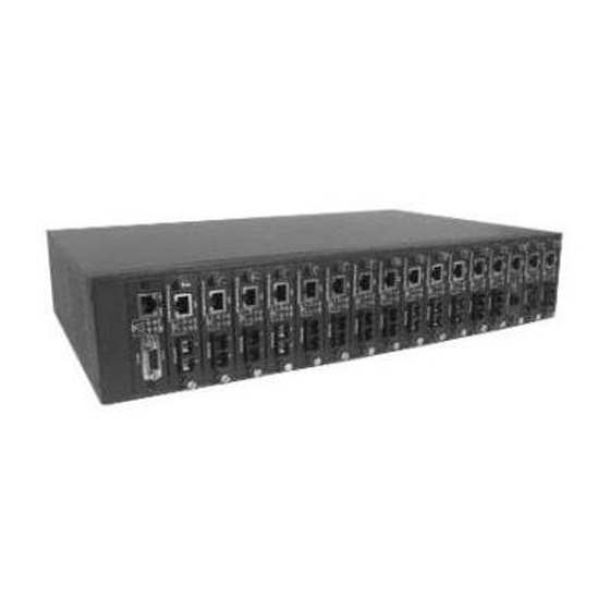
- Page 1 Raven Series Modular Media Converter System MIL-RCM16A-V2 16 Slot Raven Conversion Modules Managed Chassis with AC Power Supply USER GUIDE...
- Page 2 Transition Networks will in no case cover damages arising out of the product being used in a negligent fashion or manner. Trademarks The MiLAN logo and Transition Networks trademarks are registered trademarks of Transition Networks in the United States and/or other countries. To Contact Transition Networks...
- Page 3 FCC Warning This Equipment has been tested and found to comply with the limits for a Class A digital device, pursuant to Part 15 of the FCC rules. These limits are designed to provide reasonable protection against harmful interference in a residential installation.
-
Page 4: Table Of Contents
Content Content .................. 4 Introduction ................1 Features....................1 Software Feature ..................2 Management Methods ................4 Console and Telnet Management............4 Web-based Management ..............4 SNMP Network Management ............4 Package Contents ..................5 Hardware Description ............6 Physical Description .................6 Front & Rear Panel ...................6 LED Indicators ..................7 System Cabinet .................7 Connecting to the Network.......... - Page 5 SNMP Trap .....................21 Secure IP for Telnet, HTTP and SNMP ..........22 Port Counters..................23 Fan Status ....................23 Save Current Settings................24 Factory Default Settings & Reboot System..........24 Reboot System ..................25 TFTP Configuration ................25 Web-Based Management ............ 26 About Web-based Management .............26 System Login ..................27 Modules settings..................29 Port Counter ...................34 IP Config ....................35...
-
Page 6: Introduction
Introduction The 16 Slots intelligent converter chassis is a combination of 16-slot host cabinet and several of optional media converter bracket modules. A maximum 16-bracket module can be installed in the cabinet with two redundant power supplies. The Power supply supports AC input type with load sharing redundant feature. -
Page 7: Software Feature
100/1000TX to Gigabit fiber module, 100/1000TX to Mini-GBIC module, and 100FX WDM module 100FX and Gigabit modules support single mode or multi mode fiber Supports TS-1000 on 10/100TX to 100FX module and 100FX WDM module Event log and SNMP Trap supported SNMP MIB II and private MIB supported Supports Simple Network Time Protocol (SNTP) Power and Fan Detect... - Page 8 Software Upgra de Firmware upgrade by Web interface and TFTP Each module supports LLF feature. It can be set by Web or CLI menu LLF Mode TX → → → → Fiber: TX port link down, the fiber Link Loose Forward port will be forced down LLF Mode Fiber →...
-
Page 9: Content
Management Methods The 16 Slots intelligent converter chassis supports following management methods: Console and Telnet Management Web-based Management SNMP Network Management Console and Telnet Management Console Management is done through the RS-232 Console Port that requires a direct connection between PC and the Device. Once the Device is on the network, you can use Telnet program to Log in and modify the configuration. -
Page 10: Package Contents
Package Contents Unpack the carton of the 16 Slots intelligent converter chassis and verify them against the checklist below: 16 Slots intelligent converter chassis Power Cord Four Rubber Pads RS-232 cable User Manual 16 Slots intelligent converter chassis Rubber Pads Rack-mounted Kit RS-232 cable User Manual... -
Page 11: Hardware Description
Hardware Description The 16 Slots intelligent converter chassis is a modular unit that contains 16 slots and 2 power slots. All optional models come with the built-in CPU, and the RS-232 port is used for Out-of-Band Management and one Ethernet RJ-45 connector is for In-band management that both in front panel. -
Page 12: Led Indicators
install two units with the same power type. The Factory Default is one power module unit and one Fan Unit. Power Slot B is installed a FAN unit Power Slot A with AC Power Module Rear Panel of the 16 Slots intelligent converter chassis LED Indicators All LED status indicators are located on the front panel of the modules. - Page 13 Status Meaning Blink System kernel is working correctly Ready (Green) Green Power on Green Power Module A Ready Good A Power Module A Not Ready Green Power Module B Ready Good B Power Module B Not Ready Orange Power Module A Fail Fail A Power Module A Ready Orange...
- Page 14 Ethernet port is connected with the Green device. LK/ACT Blink The port is receiving or transmitting data Yellow Ethernet is linked with Full Duplex mode Blink Collision of Packets occurs in the port. Descriptions of the System and CPU LED...
-
Page 15: Connecting To The Network
Connecting to the Network This chapter provides the installation procedure. Pre-Installation Requirements Before to start hardware installation, make sure the installation environment has following items: PCs with 10/100Base-TX Ethernet cards: The PC must have a standard Ethernet interface to connect with the Device. UTP/STP cable with RJ-45 connector: Check the cable and connectors work properly. -
Page 16: Desktop Installation
Desktop Installation Set the device on a sufficiently large flat space with a power outlet nearby. And, the surface where user put the device should be clean, smooth, level, and sturdy. Please make sure there is enough spacing around the device to allow attaching of cables, power cord and air circulation. -
Page 17: Power On
Attach mounting brackets with screws 2. After attached both mounting brackets, position the device in the rack by lining up the holes in the brackets with the appropriate holes on the rack. Securing the device to the rack with a screwdriver and the rack-mounting screws. -
Page 18: Diagnostic Test
the power switch on. Check the front panel Power indicator to see if power is properly supplied. The device with the universal power supply, so there is no more adjustment needed. Diagnostic Test After the installation is completed and AC power is applied to the device properly, the system will automatically perform a diagnostic testing. - Page 19 Connecting the Device to a terminal via RS-232 cable After connected to the Console port, turn the PC or terminal on and configure its communications parameters to match the following default characteristics of the console port: Baud Rate: 9600 bps Data Bits: 8 Stop Bit: 1 Parity: none...
- Page 20 The Main Menu...
-
Page 21: Console Management
Console Management In this chapter, console management will be described individual function. In fact, console management mode is a line menu mode. User can enter the number of function to configure the function. Device Setting Select Device settings (Type “1” and press “Enter”) from the main menu. It displays the list of device settings items, ex: system name, location, IP…... - Page 22 3. Contact: the description for the contact people of device(Character maximum length is 64) 4. IP Address: The IP address of the device(The default IP is 192.168.16.77) 5. Subnet Mask: The default value is 255.255.255.0 6. Default Gateway: The default value is 192.168.16.254 7.
-
Page 23: Modules Settings
Q. Quit: Exit from the current configuration interface Remember to return the Main Menu to Save the modified settings, and then reboot the device. User may have to press Enter again when the device is finished reboot. Modules Settings Configure the operation mode of the media converter modules. Input “2”... - Page 24 Module setting interface (support TS-1000 module) 1. Module enable/disable: Enable or disable module function (The default is “Enable”). 2. LLF enable/disable: When the RJ-45 or Fiber is link down, it will force the other port disconnect automatically. The forced way is depends on the RJ-45 control Fiber or Fiber control RJ-45 port.
-
Page 25: Redundant Power Status
function. Enable means before the remote converter power off, the remote converter will send out the alarm notice to the central manager converter 3. In-Band Loop Back Test: Checking the fiber port connection status between remote and central site converter. User needs to set a transfer value, and verify the return value is for verifying if the value the same as user has set 4. -
Page 26: Events Log
module, on the left is power A, and on the right is power B. In main menu interface, enter “3” and press enter. Then, user will see as the following figure. Redundant Power Status interface Events Log The system provides 4095 event records 1. -
Page 27: Secure Ip For Telnet, Http And Snmp
2. Trap community: The Trap station must have same community string and can get trap information from this device(The maximum trap community string length is 32 characters. The default community string is “public”) 3~4. Trap IP 1~4: Assign the trap station’s IP address. Only the authorized station can receive the Trap information Q. -
Page 28: Port Counters
function 2. Secure IP for HTTP: To Enable or disable the secure HTTP IP function 3. Secure IP for SNMP: To Enable or disable the secure SNMP IP function 4~7. Secure IP 1~4: Assigning the IP that can manage the device through Telnet, HTTP and SNMP Q. -
Page 29: Save Current Settings
Save Current Settings After modifying, the parameters still not save in the system. User need to do the save action, then all the parameters will be stored in system Flash Rom. The values will be effect after reboot. Enter “R” and press “Enter” key to save the current settings. -
Page 30: Reboot System
Reboot System To reboot the system without set the system configuration back to default. Enter “R” and press “Enter” key. TFTP Configuration Use TFTP function to update the firmware 1. Set TFTP Server IP: set up the TFTP server IP address 2. -
Page 31: Web-Based Management
Web-Based Management About Web-based Management The 16 Slots intelligent converter chassis support embedded HTML web manage. It offers advanced management features and allows users to manage the device from anywhere on the network through a standard browser such as Microsoft Internet Explorer. The Web-Based Management supports Internet Explorer 5.0. -
Page 32: System Login
JDK/JRE download page System Login Follow the step below to login system Start Internet Explorer Key in” http://” + “the IP address of the 16 Slots intelligent converter chassis” (for example, the Factory default is 192.168.16.77) and press “Enter” key. The authentication Window The authentication screen appears... - Page 33 Key in the user name and password. The default is “root” for both Press “Enter” or Click ”OK”, then the Home Screen of the Web-based management appear right after Web management Home interface The Home page displays the configuration of the 16 Slots intelligent converter chassis.
-
Page 34: Modules Settings
IP Config page. Default is 255.255.255.0 Default Gateway: The default gateway of the managed unit that can be modified in IP Config page. Factory Default is 192.168.16.254. MAC Address: The MAC address of the managed unit. It is read only Console: display console parameter information Redundant Power status: Display the redundant power status Firmware Version: The firmware version of the management unit. - Page 35 Module State: It displays the module current status. User can enable or disable the module state. When the state is disabling, this module cannot be configured Mode: It shows the module mode. The mode was auto detected by system when installed on the device. When the mode is TS-1000, it means this module supports TS-1000 standard and then click TS-1000 configuration button to configure the TS-1000 function LLF enable/disable: When the RJ-45 or Fiber is link down, it will force the...
- Page 36 TS-1000 setting interface Central TS-1000 RJ-45 port setting: The RJ-45 port of the central site setting. Link: The port link status Speed: Configure the port speed in force negotiation mode – 100Mbps or 10 Mbps Duplex: When the port negotiation is in force mode, user can configure duplex mode –...
- Page 37 Central TS-1000 reset default: Set the configuration back to the default settings And then, click Apply to apply the configuration Terminal TS-1000 RJ-45 port setting: The RJ-45 port of the terminal site setting. When the connection is established between the central site, user are able to configure the terminal site Link: the port link status Speed: Configure the port speed in force negotiation mode –...
- Page 38 Power off Alarm (POA): To enable or disable the power off alarm function. Enable -- before the remote converter power off, the remote converter will send out the alarm notice to the central manager converter And then, click Apply to apply the configuration RJ-45 Port Link: Showing the RJ-45 port current link status Nego: Select the negotiation mode...
-
Page 39: Port Counter
Port Counter Display all port counter information in here Refresh Click to get current information Rx Good Pkts(R): Amount of good packets has received/R means RJ-45 port Rx Bad Pkts(R): Amount of good packets has received/R means RJ-45 port Tx Good Pkts(R): Amount of good packets has transmitted/R means RJ-45 port Tx Bad Pkts(R): Amount of bad packet has transmitted/R means RJ-45 port... -
Page 40: Ip Config
Port Counter interface IP Config Changing of the IP address, subnet mask, and default gateway. Just simply fill in the new IP address, subnet or default gateway in corresponding column. Then, click Apply to have the configuration taken effect. Users should reboot system to restore the new settings. -
Page 41: Snmp
SNMP Configuring device name, location, contact, the "get request", "set request" and Trap community string. The default value of get request, set request and Trap community is “ public ”. These three parameters must be correctly to performed "get request" from the management unit, "set request" to the management unit and send trap to the management unit, then click Apply to have the... -
Page 42: Event Log
Event Log To enable the event log function and view the event logs Enable Click to enable the event log function Refresh Or, press to get the event logs. The system will not auto refresh the event log Disable To stop the event log function, click To clear all event logs in the display frame, press Clear All Event Log interface... -
Page 43: Miscellaneous Settings
Miscellaneous Settings Enable/Disable Telnet: User can enable or disable the remote telnet function. The default value is “enable” Apply And then, click to have the configuration taken effect Enable/Disable HTTP: To enable or disable the remote HTTP function. The default value is “enable” And then, Click Apply to have the configuration taken effect. - Page 44 Password (max 15): Key in the new password(The maximum of length is 15 characters) Confirm Password: Re-enter the new password for confirmation Misc Settings Interface Security IP: Configure security management for Telnet, Web management and SNMP, and the maximum number of stations are 4, if the function is...
-
Page 45: Save And Reboot
enabled then only the authorized station that with right IP address can manage this device. Secure IP 1~4: Assign the IP that can manage the device through Telnet, HTTP and SNMP Secure IP for Telnet: To enable or disable the secure Telnet IP function Secure IP for HTTP: To enable or disable the secure HTTP IP function... -
Page 46: Upgrade
Save and Reboot interface Upgrade User can on-line upgrade the firmware of the device or use TFTP to update the firmware Upgrade Firmware (using HTTP to update the firmware) Using http to download the new version of firmware from vendor web site Enter password in the "... -
Page 47: Help
Upgrade interface Tftp Update( using tftp to update the firmware) TFTP Server IP: set up the TFTP server IP address File Name: set up the firmware file name Click the Tftp Upgrade button to start updating. Help In each configuration section, user can click “Help” and the help window will pop... -
Page 48: Snmp Management
SNMP Management This section describes how to configure and manage the device by accessing Management Information Base (MIB) objects with the SNMP protocol. SNMP Management The device’s MIB options are accessible through SNMP. Also, instead of defining a large set of commands, SNMP performs all operations using the “GET”, “GETNEXT”... - Page 49 Specify an SNMP object in a network device and then GETNEXT retrieve information about the rest of SNMP objects in the device Modify and store values of SNMP objects in a network device Replying the GET, GETNEXT, and SET commands are RESPONSE sent by SNMP agent A message sent by an SNMP agent to an SNMP...
-
Page 50: Specification
Specification This section provides the specifications of the converter modules IEEE802.3 10BASE-T IEEE802.3u 100BASE-TX and 100BASE-FX with N-way auto negotiation Standards IEEE802.3ab Gigabit copper with N-way auto-negotiation IEEE802.3z for Gigabit fiber 100FX Module: Fiber: Duplex ST/SC, Simplex SC (WDM single mode) RJ-45: CAT-5 (10/100Mbps) Twisted Pair cable Gigabit Module:... - Page 51 Internal Packet Gap 960ns Filter illegal Error packet CPU Module CPU Ready, Power Good (A, B) Power Fail (A, B), TX (link/Act, FDX) 100FX Module Power, TX (Link /Act, speed, FDX), FX (Link /Act, FDX) Gigabit Module LED Indicators Power, Gigabit Copper (Speed, 1000Mbps, LK/ACT, FDX/COL), Fiber (Link/Act, FDX/COL) 100/1000TX to MINI GBIC module...
- Page 52 100Mbps Multi-Mode: TX (–19dBm), RX (-31dBm), Power budget (12dBm) 100Mbps Single-mode (30KM): TX (–15 dBm), RX (-34 dBm), Power budget (19dBm) Gigabit SX Transceiver: TX (–9.5dBm), RX (12.5 dBm), Power budget (3dBm) Gigabit LX Transceiver: TX (–9.5dBm), RX (-20 dBm), Power budget (10.5dBm) 64 to 1518 Bytes for Non-VLAN Ethernet packet Transparent packet 68 to 1522 Bytes for VLAN-Tag type Ethernet...
Need help?
Do you have a question about the Milan Raven Series and is the answer not in the manual?
Questions and answers