Table of Contents
Advertisement
Quick Links
Transition Networks
M/GE-xSW-SFP-01-xx-UxX Series
Mini Gigabit Ethernet Uni-Directional Media Converter
User Guide
Unidirectional data transmissions over one strand of fiber to, or from, secure networks
Applications require a transmit-only converter to be paired with a receive-only converter
Support dual speed 100/1000Mbps SFP modules
Unit and Port LEDs for quick status
Auto MDI/MDX configuration and Jumbo Frame support
Auto-Negotiation on the 10/100/1000 copper port
Enterprise Grade, Hardened Grade, and PoE-Powered Hardened Grade converters available
Contents
1. Introduction . ............................................................................................................................................................. 2
Feature Benefits ....................................................................................................................................................... 2
Ordering Information ............................................................................................................................................... 2
Family Portrait .......................................................................................................................................................... 4
Applications .............................................................................................................................................................. 4
Application Examples ............................................................................................................................................... 5
Package Contents and Unpacking ............................................................................................................................ 6
Power Cord Included ................................................................................................................................................ 6
For More Information . .............................................................................................................................................. 6
Related Manuals . ...................................................................................................................................................... 6
2. Installation . ............................................................................................................................................................... 7
Cautions and Warnings ............................................................................................................................................ 7
Electrostatic Discharge (ESD).................................................................................................................................... 7
Front Panel Copper and Fiber Ports ......................................................................................................................... 7
Connect Fiber Cables . ............................................................................................................................................... 8
Connect Twisted-pair Copper Cable . ........................................................................................................................ 9
Insert and Connect the SFP .................................................................................................................................... 1 0
Removing an SFP Module . ...................................................................................................................................... 1 1
Mounting Options .................................................................................................................................................. 1 1
Installing DIN Rail Clip . ............................................................................................................................................ 1 2
Connecting Power .................................................................................................................................................. 1 3
3. Operation ............................................................................................................................................................... 1 4
Status LEDs ............................................................................................................................................................. 1 4
Feature Descriptions .............................................................................................................................................. 1 5
Fiber Cable and Optic Specifications ...................................................................................................................... 1 7
4. Related Information . .............................................................................................................................................. 1 9
Specifications . ......................................................................................................................................................... 1 9
Troubleshooting ..................................................................................................................................................... 2 0
Contact Us .............................................................................................................................................................. 2 1
Compliance Information . ........................................................................................................................................ 2 1
Electrical Safety Warnings ...................................................................................................................................... 2 3
Record of Revisions ................................................................................................................................................ 2 3
33781 Rev. A
M-GE-xSW-SFP-01-xx-UxX Series User Guide
https://www.transition.com/
Page 1 of 23
Advertisement
Table of Contents

Related Manuals for Transition Networks M/GE-xSW-SFP-01-xx-U Series


Summary of Contents for Transition Networks M/GE-xSW-SFP-01-xx-U Series
-
Page 1: Table Of Contents
Transition Networks M‐GE‐xSW‐SFP‐01‐xx‐UxX Series User Guide M/GE‐xSW‐SFP‐01‐xx‐UxX Series Mini Gigabit Ethernet Uni‐Directional Media Converter User Guide Unidirectional data transmissions over one strand of fiber to, or from, secure networks Applications require a transmit‐only converter to be paired with a receive‐only converter Support dual speed 100/1000Mbps SFP modules Unit and Port LEDs for quick status Auto MDI/MDX configuration and Jumbo Frame support Auto‐Negotiation on the 10/100/1000 copper port Enterprise Grade, Hardened Grade, and PoE‐Powered Hardened Grade converters available Contents 1. Introduction ................................ 2 Feature Benefits ............................... 2 Ordering Information ............................... 2 Family Portrait ................................ 4 Applications ................................ 4 Application Examples ............................... ... -
Page 2: Introduction
Transition Networks M‐GE‐xSW‐SFP‐01‐xx‐UxX Series User Guide 1. Introduction Transition Networks M/GE‐xSW‐SFP‐01‐xx‐UxX Series are 10/100/1000Base‐T to 100/1000Base‐X Mini Gigabit Ethernet Uni‐Directional Media Converters. Uni‐directional communication is often used to safeguard information in secure environments such as government agencies and military networks. A uni‐directional device, sometimes referred to as a uni‐directional security gateway or a data diode, provides a connection between two or more networks with different security classifications and helps to protect assets by ensuring information is directed only to, or from, the appropriate network as designated by the directional device. Uni‐directional media converters combine this one‐way communications with the benefits of a copper to fiber media converter. Media converters are generally cost‐effective, plug‐and‐play devices that allow fiber optic cabling to be connected to copper‐based networking equipment. The deployment of fiber adds a layer of security to networks as it is difficult to tap into fiber and go undetected. If threats are attacking a network, the fiber links usually go down and network administrators are made aware of the problem, providing them the opportunity to address a potential breach of security. Adding uni‐directional technology to a media converter creates a physically secure one‐way communication channel between a secure network and an unsecure network. These devices can be used to allow data from a classified, high‐security area to be transmitted to a low‐security area, while preventing unsecure data from reentering the classified network. An alternative application allows a secure network to be updated with data from an external source while ensuring its critical data is unable to leave the classified area. Feature Benefits Uni‐directional data transmissions to, or from, secure networks. Simplex communications only requires one strand of fiber cable. Applications require a transmit‐only converter to be paired with a receive‐only converter. Converters support dual speed 100/1000Mbps SFP modules offering great flexibility to meet network requirements. Converters use duplex SFP modules but the transmitting converter only uses the TX port on the SFP, while the RX port is deactivated. Likewise the receiving converter only uses the RX port, while the TX port is deactivated. ... - Page 3 Transition Networks M‐GE‐xSW‐SFP‐01‐xx‐UxX Series User Guide The M/GE‐xSW‐SFP‐01‐xx‐UxX series includes: SKU Description Enterprise Grade Converters (0°C to +50°C) 10/100/1000Base‐T (RJ‐45) [100 m/328 ft.] to 100/1000Base‐X SFP M/GE‐PSW‐SFP‐01‐UTX Slot (empty) Uni‐directional Transmitting Converter M/GE‐PSW‐SFP‐01‐URX 10/100/1000Base‐T (RJ‐45) [100 m/328 ft.] to 100/1000Base‐X SFP Slot (empty) Uni‐directional Receiving Converter Hardened Grade Converters (‐40°C to +75°C) Hardened Mini 10/100/1000Base‐T (RJ‐45) to 100/1000Base‐X Open M/GE‐ISW‐SFP‐01‐UTX SFP Slot Uni‐directional Transmitting Converter Hardened Mini 10/100/1000Base‐T (RJ‐45) to 100/1000Base‐X Open M/GE‐ISW‐SFP‐01‐URX SFP Slot Uni‐directional Receiving Converter PoE‐Powered Hardened Grade Converters (‐40°C to +75°C) PoE Powered Hardened Mini; 10/100/1000Base‐T (RJ‐45) to 100/1000Base‐X Open SFP Slot Uni‐directional Transmitting M/GE‐ISW‐SFP‐01‐PD‐UTX Converter PoE Powered Hardened Mini; 10/100/1000Base‐T (RJ‐45) to M/GE‐ISW‐SFP‐01‐PD‐URX 100/1000Base‐X Open SFP Slot Uni‐directional Receiving Converter Power Supply Options Power Supply, 24VDC to 60VDC input Stand‐alone (for Enterprise SPS‐2460‐SA Converters) (must be ordered separately) External AC/DC Desktop Power Supply, 12 VDC, 18W (for Hardened SPS‐UA12DHT Non‐PD Converters) External AC/DC DIN Rail Mount Power Supply , 10.8 – 13.2 VDC, 24W, 25083 (for Hardened Non‐PD Converters) ...
-
Page 4: Family Portrait
Transition Networks M‐GE‐xSW‐SFP‐01‐xx‐UxX Series User Guide Family Portrait The figure below shows the six available SKUs in the three paired combinations. Applications The M/GE‐xSW‐SFP‐01‐xx‐UxX can be used in applications such as: Transmit data from a classified, high‐security area to a low‐security area Update secure data on a secure network from an unsecure external source These applications are shown and described below. 33781 Rev. A https://www.transition.com/ Page 4 of 23 ... -
Page 5: Application Examples
Transition Networks M‐GE‐xSW‐SFP‐01‐xx‐UxX Series User Guide Application Examples The figure below shows M/GE‐xSW‐SFP‐01‐xx‐UxX deployed to ensure a secure data environment. These devices allow data from a classified, high‐security area to be transmitted to a low‐security area, while preventing unsecure data from re‐entering the classified network. Benefits: protect assets and data, block access to the secure area, and prevent manipulation of secure data. The figure below shows a secure network that needs to be updated with data from an unsecure external source, where it can be analyzed and used to make key decisions. Unidirectional communication ensures no data is able to leave the classified area. Benefits: maintain integrity of data in secured area, block classified data from leaking out of the secured area, and allow databases to be updated with current information. 33781 Rev. A https://www.transition.com/ Page 5 of 23 ... -
Page 6: Package Contents And Unpacking
Transition Networks M‐GE‐xSW‐SFP‐01‐xx‐UxX Series User Guide Package Contents and Unpacking Verify you have received the following items. Contact your sales representative if any item is missing or damaged. Please save the packaging for possible future use. M/GE‐xSW‐SFP‐01‐xx‐UxX Series media converters (one Transmit converter & one Receive converter) Power Supply ordered and packaged separately for the M/GE‐ISW‐SFP‐01‐UxX converters. Power Supply included with the M/GE‐PSW‐SFP‐01‐UxX‐xx. Power Supply not needed with the PoE powered M/GE‐ISW‐SFP‐01‐PD‐UxX. Mounting Brackets (ordered and packaged separately) Documentation Postcard Power Cord Included To order the corresponding country‐specific power cord, add the extension to the end of the SKU (for M/GE‐PSW‐SFP‐01‐UTX‐xx and M/GE‐PSU‐SFP‐01‐URX‐xx only): ‐NA = North America, ‐LA = Latin America, ‐EU = Europe, ‐UK = United Kingdom, ‐SA = South Africa, ‐JP = Japan, ‐OZ = Australia, and ‐BR = Brazil. For More Information For Transition Networks Drivers, Firmware, etc. go to the Product Support webpage (logon required). For Transition Networks Manuals, Brochures, Datasheets, etc. go to the Support Library (no logon required). Note: Information in this document is subject to change without notice. Note that this manual provides links to third party web sites for which Transition Networks is not responsible. Related Manuals SPS‐2460‐SA Power Supply User Guide, 33455 SPS‐UA12DHT Power Supply Datasheet 25083 Power Supply Datasheet WMBM Wall‐Mount Bracket Install Guide, 33393 ... -
Page 7: Installation
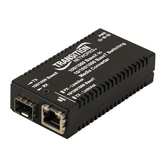
Transition Networks M‐GE‐xSW‐SFP‐01‐xx‐UxX Series User Guide 2. Installation Cautions and Warnings Cautions indicate that there is the possibility of poor equipment performance or potential damage to the equipment. Warnings indicate that there is the possibility of injury to person. Cautions and Warnings appear here and may appear throughout this manual where appropriate. Failure to read and understand the information identified by this symbol could result in poor equipment performance, damage to the equipment, or injury to persons. See Electrical Safety Warnings on page 23 for Electrical Safety Warnings translated into multiple languages. Electrostatic Discharge (ESD) Observe these ESD precautions when installing or handing the M/GE‐xSW‐SFP‐01‐xx‐UxX: Do not remove the converter from its protective packaging until you are ready to install M/GE‐xSW‐SFP‐01‐xx‐ UxX Series media converter. Wear an ESD wrist grounding strap before handling the M/GE‐xSW‐SFP‐01‐xx‐UxX Series media converter or its component. If you do not have a wrist strap, maintain grounded contact with the unit throughout any procedure requiring ESD protection. Front Panel Copper and Fiber Ports The figure below shows the front panel of the M/GE‐xSW‐SFP‐01‐xx‐UxX Series media converters. 33781 Rev. A https://www.transition.com/ Page 7 of 23 ... -
Page 8: Connect Fiber Cables
Transition Networks M‐GE‐xSW‐SFP‐01‐xx‐UxX Series User Guide Connect Fiber Cables Full duplex (always ON) is on the fiber side only, therefore, the 512‐Bit Rule does not apply. Cable lengths are constrained by the cable requirement. 1. Use a 1000Base‐SX or ‐LX10 fiber cable with male, two‐stranded TX to RX connectors at each end. 2. Connect the fiber cable to the M/GE‐xSW‐SFP‐01‐xx‐UxX Series media converters as follows: Connect the male TX cable connector to the female TX port. Connect the male RX cable connector to the female RX port. 3. Connect the fiber cable to the other device (media converter, hub, etc.) as follows: Connect the male TX cable connector to the female RX port. Connect the male RX cable connector to the female TX port. Connecting Single-strand Fiber Cable Single‐strand fiber cable can only be used if the SFP module installed in the converter also supports bi‐directional single strand fiber. The uni‐directional functions of these converters are controlled within the converter, therefore a duplex fiber cable can be used. Or, a simplex fiber cable can be used between the transmitting converter and the receiving converter. Additionally, bi‐ directional single‐strand fiber can be used with these converters. If using a simplex single‐strand fiber cable, it is OK to leave open the unused Receive port or unused Transmit port on the converters; the converter will not try to transmit or receive data on these unused ports. 33781 Rev. A https://www.transition.com/ Page 8 of 23 ... -
Page 9: Connect Twisted-Pair Copper Cable
Transition Networks M‐GE‐xSW‐SFP‐01‐xx‐UxX Series User Guide Connect Twisted-pair Copper Cable The AutoCross feature allows either MDI (straight‐through) or MDI‐X (crossover) cable connections to be configured automatically, according to network conditions. If half‐duplex mode is used, refer to the 512‐Bit Rule. If full‐duplex mode is used, the 512‐Bit Rule does not apply. The cable lengths are constrained by the cable requirements. Perform these steps: Locate a 10Base‐T or 100Base‐TX cable with RJ‐45 connectors installed at both ends. Connect the RJ‐45 connector at one end of the cable to the RJ‐45 port on the M/GE‐xSW‐SFP‐01‐xx‐UxX Series media converter. Connect the RJ‐45 connector at the other end of the cable to the RJ‐45 port on the other device (switch, workstation, etc.). 33781 Rev. A https://www.transition.com/ Page 9 of 23 ... -
Page 10: Insert And Connect The Sfp
Transition Networks M‐GE‐xSW‐SFP‐01‐xx‐UxX Series User Guide Insert and Connect the SFP These converters support dual speed 100/1000Mbps SFP modules. Perform the steps below to install an SFP in the M/GE‐PSW‐SFP‐01. Refer to the documentation that came with your SFP for specific requirements. See our website for full details on our SFP products. 1. Remove the SFP transceiver module from its protective packaging. Note: Do not remove the optical bore dust plugs until directed to do so in a later procedure. 2. Check the slot orientation. Position the SFP device at the desired installation slot, with the label facing correctly. 3. Carefully slide the SFP device into the slot, aligning it with the internal installation guides. 4. Ensure that the SFP device is firmly seated against the internal mating connector. 5. Remove the dust plug from the connector. Save the dust plug for future use. 6. Connect the fiber cable to the fiber port connector of the SFP device. Make sure the SFP release latch is in the up (closed) position when you insert the cable connector into the SFP. 7. Attach the other end of the cable into the other device. 33781 Rev. A https://www.transition.com/ Page 10 of 23 ... -
Page 11: Removing An Sfp Module
Transition Networks M‐GE‐xSW‐SFP‐01‐xx‐UxX Series User Guide Removing an SFP Module Caution: Be careful when removing the SFP from a device. Some SFP transceiver module temperatures may exceed 160°F (70°C) and be too hot to touch with bare hands. Note: Do not remove and replace the SFP modules more often than necessary; excessive SFP removing and replacing can shorten the SFPs useful life. 1. Attach an ESD‐preventive wrist strap to your wrist and to the ESD ground connector or a bare metal surface on your chassis. 2. For future reattachment of fiber‐optic cables, note which connector plug is send (TX) and which is receive (RX). 3. Remove the SFP transceiver module: a. If the SFP transceiver module has an actuator button latch, gently press the actuator button on the front of the SFP transceiver module until it clicks and the latch mechanism releases the SFP transceiver module from the socket connector. Grasp the actuator button between your thumb and index finger, and carefully pull the SFP transceiver module straight out of the module slot. b. If the SFP transceiver module has a bail clasp latch, pull the latch out and down to eject the SFP transceiver module from the socket connector. If the bail clasp latch is obstructed and you cannot use your index finger to open it, use a small, flat‐blade screwdriver or other long, narrow instrument to open the bail clasp latch. Grasp the SFP transceiver module between your thumb and index finger, and carefully remove it from the socket. 4. Replace the Dust Plug. 5. Place the removed SFP transceiver module in an antistatic bag or other protective package. Mounting Options The M‐GE‐xSW‐SFP‐01‐xx‐UxX supports the following Mounting options. See Related Manuals on page 6 for links to Mounting option information. WMBM: Wall Mount Bracket for Mini (for Enterprise Converters) M‐MCR‐01: 18‐Slot Powered Mini Chassis (for Enterprise Converters) DRBM: DIN Rail Mount Bracket for Mini (for Enterprise Converters) RMBM: Rack Mount Bracket for Mini, use with RMS19‐SA4‐02 and/or E‐MCR‐05 33781 Rev. A https://www.transition.com/ Page 11 of 23 ... -
Page 12: Installing Din Rail Clip
Transition Networks M‐GE‐xSW‐SFP‐01‐xx‐UxX Series User Guide Installing DIN Rail Clip To install the DIN rail onto the media converter (parts are shown right): 1. Position the DIN rail clamp to the side of the media converter as shown below. 2. Position the 4‐40 screw to attach the DIN rail to the media converter as shown above left. 3. Insert and tighten the 4‐40 screw until the DIN rail clip appears as shown above right. When the DIN Rail Clip is attached, there should be no gap between the Clip and the media converter as shown below. 33781 Rev. A https://www.transition.com/ Page 12 of 23 ... -
Page 13: Connecting Power
Transition Networks M‐GE‐xSW‐SFP‐01‐xx‐UxX Series User Guide Connecting Power The uni‐directional converters are available in three power options DC input with a barrel connector for an external AC/DC power supply DC input with a terminal block PoE powered media converter M/GE‐PSW‐SFP‐01‐UTX‐NA and M/GE‐PSW‐SFP‐01‐URX‐NA: Power input: Barrel Connector. Supporting 4.5VDC to 14VDC. External AC/DC power supply: Input: 100 to 240 VAC. Output: 12VDC. M/GE‐ISW‐SFP‐01‐PD‐UTX and M/GE‐ISW‐SFP‐01‐PD‐URX: Power input: RJ‐45. Supporting IEEE802.3af PoE PD Standard. M/GE‐ISW‐SFP‐01‐UTX and M/GE‐ISW‐SFP‐01‐URX: Power input: Terminal Block. Supporting 12 – 48 VDC and 24 ‐36 VAC. You can use your own power source, or you can use one of the three power supply options that Transition Networks offers (see below). Power Supply Options The M‐GE‐xSW‐SFP‐01‐xx‐UxX supports the following Power Supply options. SPS‐2460‐SA: Power Supply, 24VDC to 60VDC input Stand‐alone (for Enterprise Converters) (must be ordered separately) SPS‐UA12DHT: External AC/DC Desktop Power Supply, 12 VDC, 18W (for Hardened Non‐PD Converters) 25083: External AC/DC DIN Rail Mount Power Supply , 10.8 – 13.2 VDC, 24W, (for Hardened Non‐PD Converters) See Related Manuals on page 6 for links to power supply information. 33781 Rev. A https://www.transition.com/ Page 13 of 23 ... -
Page 14: Operation
Transition Networks M‐GE‐xSW‐SFP‐01‐xx‐UxX Series User Guide 3. Operation Status LEDs Use the status LEDs to monitor the M/GE-xSW-SFP-01-xx-UxX Series media converter operation in the network. LED descriptions are as follows: TP LED Blink Rate The TP LED flash rate indicates the copper network speed: Pulses/second Blink Rate Speed Indicated 12 pps every 84 ms 1000Mbps (1Gbps) 6 pps every 170 ms 100Mbps 3 pps ... -
Page 15: Feature Descriptions
Transition Networks M‐GE‐xSW‐SFP‐01‐xx‐UxX Series User Guide SFP (Fiber) LED Operation The SFP (Fiber) LED (the middle LED) indicates Link of 100Mbps or 1Gbps (see below). LED operation of paired M/GE‐ISW‐SFP‐01‐PD‐UTX and M/GE‐ISW‐SFP‐01‐PD‐URX in different scenarios TX Converter RX Converter Scenario TX LED L/A LED RX LED L/A LED All Links Down ON OFF OFF OFF All Links up, but no data transfer ON ON ON ON Data moving in the TX to RX converter direction Flashing ON Flashing Flashing Data moving in the RX to TX converter direction ON ON Flashing Flashing Feature Descriptions ™... -
Page 16: Flow Control
Transition Networks M‐GE‐xSW‐SFP‐01‐xx‐UxX Series User Guide the round‐trip delay in bit‐times (BT) of a particular collision domain. If the result is less than or equal to 512 BT, the path is good. Flow Control The process of adjusting the flow of data from one device to another ensures that the receiving device can handle all of the incoming data. This is particularly important where the sending device is capable of transmitting data much faster than the receiving device can accept it. Rate Conversion The M/GE‐xSW‐SFP‐01‐xx‐UxX Series media converters allow connection of 10Mb/s terminal devices on a 10Base‐ T legacy Ethernet copper network to 100Mb/s terminal devices on a 100Base‐TX Fast Ethernet copper network and/or to 100Mb/s terminal devices on a 100Base‐FX or –LX10 Fast Ethernet fiber network. Distance Extension The M/GE‐xSW‐SFP‐01‐xx‐UxX Series media converters can segment one (1) 10Base‐T copper Ethernet and/or 100Base‐TX copper Fast Ethernet, and one (1)100Base‐FX or –LX10 fiber Fast Ethernet collision domain: In a half‐duplex Ethernet or Fast Ethernet environment, the M/GE‐xSW‐SFP‐01‐xx‐UxX Series media converters extend network distances by segmenting collision domains so that the 512‐Bit Rule applies separately to each collision domain. In a full‐duplex Ethernet or Fast Ethernet environment, the M/GE‐xSW‐SFP‐01‐xx‐UxX Series media converters extend network distances to the physical cable limitations imposed by the selected twisted‐ pair copper fiber cables. Far-End Fault When a fault occurs on an incoming fiber link (1), the media converter transmits a Far‐End Fault signal on the outgoing fiber link (2). In addition the Far‐End Fault signal also activates the Link Pass‐Through, which in turn, disables the link on the copper portion of the network (3) and (4). 33781 Rev. A https://www.transition.com/ Page 16 of 23 ... -
Page 17: Fiber Cable And Optic Specifications
Transition Networks M‐GE‐xSW‐SFP‐01‐xx‐UxX Series User Guide Fiber Cable and Optic Specifications The fiber optic cable physical characteristics must meet or exceed IEEE 802.3ae specification. Fiber cable Bit Error Rate: <10‐9 Single mode fiber (recommended): 9 μm Multimode fiber (recommended): 62.5/125 μm Multimode fiber (optional): 100/140, 85/140, 50/125 μm Optics Fiber Optic Transmitter Power: depends on the SFP module used. Fiber Optic Receiver Sensitivity: depends on the SFP module used. Link Budget: depends on the SFP module used. ... -
Page 18: Copper Cable
Transition Networks M‐GE‐xSW‐SFP‐01‐xx‐UxX Series User Guide Copper Cable Category 3: (Minimum requirement for 10 Mb/s operation) Gauge 24 to 22 AWG Attenuation 11.5 dB/100m @ 5‐10 MHz Maximum Cable Distance 100 meters Category 5: (Minimum requirement for 100 Mb/s operation) Gauge 24 to 22 AWG Attenuation 22.0 dB /100m @ 100 MHz Maximum Cable Distance ... -
Page 19: Related Information
Transition Networks M‐GE‐xSW‐SFP‐01‐xx‐UxX Series User Guide 4. Related Information Specifications Transition Networks M/GE‐xSW‐SFP‐01‐xx‐UxX converters are designed to meet these specifications: IEEE 802.3, IEEE 802.3z, IEEE 802.3u, IEEE 802.3ab; Standards IEEE 802.3af (PD Versions Only) Pwr (Power): On = Power Status LEDs FX‐Link/Act (Fiber Link / Activity): On = Link, Flashing = Activity TX‐Link/Act (Copper Link / Activity): On = Link, Flashing = Activity Dimensions Width: 1.8" [46 mm] x Depth: 3.3” [85 mm] x Height: 0.85” [22 mm] Power Consumption 1.8 watts without the SFP module Power Supply External AC/DC required, 12 VDC, 0.5A 4.5VDC to 14VDC (M/GE‐PSW‐SFP‐01‐UxX) Power Input 12 – 48 VDC or 24 – 36VAC (M/GE‐ISW‐SFP‐01‐UxX) IEEE 802.3af supplied through TP RJ‐45 (M/GE‐ISW‐SFP‐01‐PD‐UxX) M/GE‐PSW‐SFP‐01‐UxX: Operating Temp.: 0°C to +50°C Humidity: 5% to 95% (non‐condensing) Storage Temp: ‐15°C to +65°C Altitude: 0 to 10,000 ft. Environment M/GE‐ISW‐SFP‐01‐xx‐UxX: Operating Temp.: ‐40°C to +75°C Humidity: 5% to 95% (non‐condensing) Storage Temp.: ‐40°C to +85°C Altitude: 0 to 10,000 ft. Weight 2 lbs. [0.9 kg] Safety: Wall Mount Power Supply, UL Listed, cUL Listed (Canada); FCC Class A, ... -
Page 20: Troubleshooting
Transition Networks M‐GE‐xSW‐SFP‐01‐xx‐UxX Series User Guide Troubleshooting If the media converter fails, isolate and correct the fault by answering the following questions and then taking the indicated action: 1. Is the PWR (power) LED lit? NO • Is the power adapter the proper type of voltage and cycle frequency for the AC outlet? • Is the power adapter properly installed in the media converter and in the outlet? • Contact Tech Support. See Contact Us below. YES • Proceed to step 2. 2. Is the RXC (copper link) LED lit? NO • Check the twisted‐pair copper cables for proper connection. • Contact Tech Support. See Contact Us below. YES • Proceed to step 3. 3. Is the LKF (fiber link) LED lit? NO • Check the fiber cables for proper connection. ... -
Page 21: Contact
Transition Networks M‐GE‐xSW‐SFP‐01‐xx‐UxX Series User Guide Contact Us Technical Support: Technical support is available 24‐hours a day US and Canada: 1‐800‐260‐1312 International: 00‐1‐952‐941‐7600 Main Office tel: +1.952.941.7600 | toll free: 1.800.526.9267 | fax: 952.941.2322 sales@transition.com | techsupport@transition.com | customerservice@transition.com Address Transition Networks 10900 Red Circle Drive Minnetonka, MN 55343, U.S.A. Web: https://www.transition.com Compliance Information Declaration of Conformity 33781 Rev. A https://www.transition.com/ Page 21 of 23 ... -
Page 22: Fcc Regulations
Transition Networks M‐GE‐xSW‐SFP‐01‐xx‐UxX Series User Guide FCC Regulations This equipment has been tested and found to comply with the limits for a Class A digital device, pursuant to Part 15 of the FCC rules. These limits are designed to provide reasonable protection against harmful interference when the equipment is operated in a commercial environment. This equipment generates, uses and can radiate radio frequency energy and, if not installed and used in accordance with the instruction manual, may cause harmful interference to radio communications. Operation of this equipment in a residential area is likely to cause harmful interference, in which case the user will be required to correct the interference at the user's own expense. Canadian Regulations This digital apparatus does not exceed the Class A limits for radio noise for digital apparatus set out on the radio interference regulations of the Canadian Department of Communications. Le présent appareil numérique n'émet pas de bruits radioélectriques dépassant les limites applicables aux appareils numériques de la Class A prescrites dans le Règlement sur le brouillage radioélectrique édicté par le ministère des Communications du Canada. European Regulations Warning This is a Class A product. In a domestic environment this product may cause radio interference in which case the user may be required to take adequate measures. Achtung ! Dieses ist ein Gerät der Funkstörgrenzwertklasse A. In Wohnbereichen können bei Betrieb dieses Gerätes Rundfunkstörungen auftreten. In diesem Fäll is der Benutzer für Gegenmaßnahmen verantwortlich. Attention ! Ceci est un produit de Classe A. Dans un environment domestique, ce produit risque de créer des interférences radioélectriques, il appartiendra alors à l'utilsateur de prende les measures spécifiques appropriées. In accordance with European Union Directive 2002/96/EC of the European Parliament and of the Council of 27 January 2003, Transition Networks will accept post usage returns of this product for proper disposal. The contact information for this activity can be found in the 'Contact Us' portion of this document. CAUTION: RJ connectors are NOT INTENDED FOR CONNECTION TO THE PUBLIC TELEPHONE NETWORK. Failure to observe this caution could result in damage to the public telephone network. Der Anschluss dieses Gerätes an ein öffentlickes Telekommunikationsnetz in den EGMitgliedstaaten verstösst gegen die jeweligen einzelstaatlichen Gesetze zur Anwendung der Richtlinie 91/263/EWG zur ... -
Page 23: Electrical Safety Warnings
Transition Networks M‐GE‐xSW‐SFP‐01‐xx‐UxX Series User Guide Electrical Safety Warnings Electrical Safety IMPORTANT: This equipment must be installed in accordance with safety precautions. Elektrische Sicherheit WICHTIG: Für die Installation dieses Gerätes ist die Einhaltung von Sicherheitsvorkehrungen erforderlich. Elektrisk sikkerhed VIGTIGT: Dette udstyr skal installeres i overensstemmelse med sikkerhedsadvarslerne. Elektrische veiligheid BELANGRIJK: Dit apparaat moet in overeenstemming met de veiligheidsvoorschriften worden geïnstalleerd. Sécurité électrique IMPORTANT: Cet équipement doit être utilisé conformément aux instructions de sécurité. Sähköturvallisuus TÄRKEÄÄ: Tämä laite on asennettava turvaohjeiden mukaisesti. Sicurezza elettrica IMPORTANTE: questa apparecchiatura deve essere installata rispettando le norme di sicurezza. Elektrisk sikkerhet VIKTIG: Dette utstyret skal installeres i samsvar med sikkerhetsregler. Segurança eléctrica IMPORTANTE: Este equipamento tem que ser instalado segundo as medidas de precaução de segurança. Seguridad eléctrica IMPORTANTE: La instalación de este equipo deberá llevarse a cabo cumpliendo con las precauciones de seguridad. Elsäkerhet OBS! Alla nödvändiga försiktighetsåtgärder måste vidtas när denna utrustning används. Record of Revisions Rev Date Notes A 6/4/19 ...
Need help?
Do you have a question about the M/GE-xSW-SFP-01-xx-U Series and is the answer not in the manual?
Questions and answers