Table of Contents

Related Manuals for Transition Networks Milan MIL-RC6113SX-V2


Summary of Contents for Transition Networks Milan MIL-RC6113SX-V2
- Page 1 Raven Series Standalone Media Converters MIL-RC6113SX-V2 -10/100/1000BASE-T / 1000BASE-SX SC MMF MIL-RC6113LX-V2 – 10/100/1000BASE-T / 1000BASE-LX SC SMF MIL-RC6113GB-V2 – 10/100/1000BASE-T / 1000BASE-X SFP Slot (Empty) USER GUIDE...
- Page 2 In no event shall Transition Networks be liable for incidental or consequential damages, costs, or expenses arising out of or in connection with the performance of the product delivered hereunder Transition Networks will in no case cover damages arising out of the product being used in a negligent fashion or manner.
- Page 3 FCC Warning This Equipment has been tested and found to comply with the limits for a Class A digital device, pursuant to Part 15 of the FCC rules. These limits are designed to provide reasonable protection against harmful interference in a residential installation. This equipment generates, uses and can radiate radio frequency energy and, if not installed and used in accordance with the instructions, may cause harmful interference to radio communications.
-
Page 4: Table Of Contents
Content Introduce........................2 .............................3 EATURES ........................5 ACKAGE ONTENTS Hardware Description ....................6 ..........................6 RONT ANEL ..........................7 ANEL ............................8 ORTS LED I ..........................9 NDICATORS DIP- ..........................10 SWITCH Converters module Installation ...................11 .............................12 ABLING Troubles shooting .......................13... -
Page 5: Introduce
Introduce The Giga Standalone Fiber Converter is a cost- effective solution for the converting 10/100/1000Base-TX (Auto MDI/MDIX) and pure 1000 Base-T to 1000Base-FX cabling. It can be slotted in Multi-Converter Chassis on up to 10 optional modular converter units, which allows your network connectivity to be more flexible. -
Page 6: Features
Features IEEE 802.3 10BASE-T IEEE 802.3u 100BASE-TX Standard IEEE 802.3ab 1000BaseT, IEEE 802.3z 1000BaseSX/LX standards IEEE 802.3x Flow Control and Back pressure Power (Green) UTP SPD: 1000Mbps /100Mbps LED Indicators Lnk/Act: UTP /FIBER FDX: UTP: Full-Duplex mode / Half-Duplex or Link down FIBER: Full-Duplex mode / Link down Fiber: Duplex SC/MINI GBIC 3.3V/ WDM RJ-45 Socket: CAT-5e (10/100/1000Mbps) Twisted Pair... - Page 7 will forced copper port to link down. Switch Store and Forward architecture 10Kbyte(Pure converter mode)/ Jumbo Frame 2Kbyte(Switch converter mode) Power Stand-alone (external adapter):DC 9V / 0.7A Power 4.3 Watts(max) Consumption Operating O℃ to 45℃ (32℉ to 113℉) Temperature Operating 10% to 90% Humidity Storage...
-
Page 8: Package Contents
Package Contents Beware of which type of converter module that you have purchased. And, please refer to the package content list below to verify them against the checklist. Stand-alone converter module package contains following items. The Giga Fiber Converter AC-DC Power Adapter User Guide Rack mount ear (only for converter chassis) Compare the contents of your Converter with the standard checklist above. -
Page 9: Hardware Description
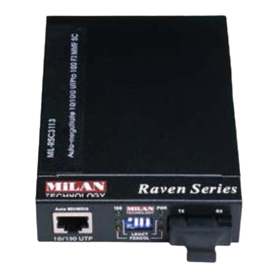
Hardware Description The Giga Fiber Converter dimension (L x W x H): 120mm x 85mm x 26mm Front Panel 10/100/1000Base-T to 1000Base-FX converter module The Front Panel of the 10/100/1000Base-T to 1000Base-FX converter module consists of one Giga Fiber port, one copper Port (Auto MDI/MDIX), and 6 LED Indicators (SPD, LK/ACT, FDX, Fiber LK/ACT, FDX/COL, and PWR). -
Page 10: Rear Panel
(1) RJ-45 Port (3) DIP-Switch (2) LED (4) Fiber Connector Rear Panel The rear panel contains a power socket. This power socket accepts DC9V voltage and minimum 0.7A supplied current. DC IN... -
Page 11: Ports
Ports Copper Port (Auto MDI/MDIX) of 10/100/1000Base-T to 1000Base-FX converter module: The Ethernet ports will auto-sense for 10Base-T, 100Base-TX, or 1000Base-T connections. Auto MDI/MDIX means that you can connect to another Switch or workstation without changing non-crossover or crossover cabling. Fiber Port: This port is for 1000Base-FX connections. -
Page 12: Led Indicators
LED Indicators There are 6 diagnostic LEDs located on the Front panel of converter module. They provide real-time information of system and optional status. The following table provides description of the LED status and their meanings for Modular Giga Fiber Converter. -
Page 13: Dip-Switch
DIP-switch The DIP-switch is used to configure operation mode for LLF (Link Lost Forwarding) and operation mode for Copper/Fiber port. The default value of Dipswitch is OFF. 10/100/1000Base-T to 1000Base-FX converter module S/W No Status Description LLF Enable LLF Disable Pure converter mode Switch converter mode Reserved... -
Page 14: Converters Module Installation
Converters module Installation This installation is only for mounted in converter chassis converter module. You can follow the steps below to install modular converters. A. Remove the blank bracket by rotating thumbscrew counterclockwise. Put the blank bracket aside, but don’t discard blanket bracket. B. -
Page 15: Cabling
Cabling Using four twisted-pair, Category 5e cabling for copper port connection. The cable between the converter and the link partner (switch, hub, workstation, etc.) must be less than 100 meters (328 ft.) long. Fiber segment using single-mode connector type must use 9/125 µm single-mode fiber cable. -
Page 16: Troubles Shooting
Troubles shooting Check the configuration DIP-switch. It must be setting in the same operation mode with the link partner. Select the proper Copper/Fiber cable to construct your network. The single-mode converter must use single-mode fiber cable. Please check that you are using the right cable.
Need help?
Do you have a question about the Milan MIL-RC6113SX-V2 and is the answer not in the manual?
Questions and answers