Table of Contents
Advertisement
Quick Links
Download this manual
See also:
User Manual
Owner's Operator and Maintenance Manual
Electric
Portable Patient Lift
DEALER: This manual MUST be given to
the user of the patient lift.
USER: BEFORE using this patient lift, read
this manual and save for future reference.
For more information regarding
Invacare products, parts, and services,
please visit www.invacare.com
Advertisement
Table of Contents
Troubleshooting

Related Manuals for Invacare Low Profile RPL450-2


Summary of Contents for Invacare Low Profile RPL450-2
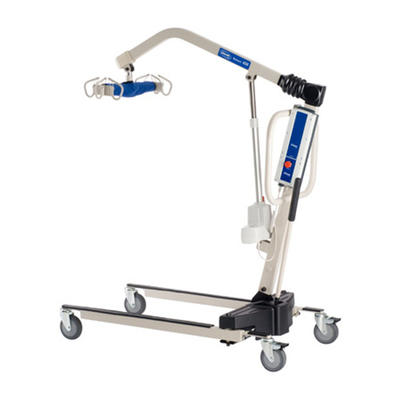
- Page 1 Portable Patient Lift DEALER: This manual MUST be given to the user of the patient lift. USER: BEFORE using this patient lift, read this manual and save for future reference. For more information regarding Invacare products, parts, and services, please visit www.invacare.com...
- Page 2 EQUIPMENT - OTHERWISE INJURY OR DAMAGE MAY RESULT. INVACARE PRODUCTS ARE SPECIFICALLY DESIGNED AND MANUFACTURED FOR USE IN CONJUNCTION WITH INVACARE ACCESSORIES. ACCESSORIES DESIGNED BY OTHER MANUFACTURERS HAVE NOT BEEN TESTED BY INVACARE AND ARE NOT RECOMMENDED FOR USE WITH INVACARE PRODUCTS. ‘...
-
Page 3: Table Of Contents
TABLE OF CONTENTS TABLE OF CONTENTS SPECIAL NOTES ................9 LABEL LOCATION ................10 SPECIFICATIONS ................11 Patient Lift ..............................11 Full Body, Divided Leg and Toileting Slings ..................12 Reliant Scale RLS6 ............................12 SECTION 1—GENERAL GUIDELINES ..........13 Assembling the Patient Lift ........................13 Operating the Patient Lift ........................13 Using the Sling ............................14 Lifting the Patient............................14... - Page 4 TABLE OF CONTENTS TABLE OF CONTENTS SECTION 4—LIFTING THE PATIENT ..........26 Introduction ...............................26 Positioning the Patient Lift........................26 Attaching a Sling............................27 Lifting/Moving the Patient ........................27 SECTION 5—TRANSFERRING THE PATIENT ........30 Introduction ...............................30 Transferring to a Commode Chair ......................31 Transferring to a Standard Commode ....................31 Transferring to a Bathing Unit.......................32 Transferring to a Wheelchair ........................32 SECTION 6—...
- Page 5 SECTION 8— ACCESSORIES ............. 42 Reliant Scale RLS6 ............................42 Removing the Swivel Bar........................42 Installing the Reliant Scale ........................43 Operating the Scale..........................44 Keypad Functions..........................44 Weighing the Patient..........................45 Replacing the Battery..........................46 Calibrating the Reliant Scale ......................46 Troubleshooting............................47 Display Codes ............................48 LIMITED WARRANTY ..............51 Part No.
- Page 6 3. Receive updates with product information, maintenance tips, and industry news. 4. Invacare can contact you or your provider, if servicing is needed on your product. 5. It will enable Invacare to improve product designs based on your input and needs.
- Page 7 11. User's Year of birth: ______________________________________________________ If at any time you wish not to receive future mailings from us, please contact us at Invacare Corporation, CRM Department, 39400 Taylor Parkway, Elyria, OH 44035, or fax to 877-619-7996 and we will remove you from our mailing list.
- Page 8 Fold here Fold here Invacare Product Registration Form Please Seal with Tape Before Mailing...
-
Page 9: Special Notes
Invacare products are specifically designed and manufactured for use in conjunction with Invacare accessories. Accessories designed by other manufacturers have not been tested by Invacare and are not recommended for use with Invacare products. Part No. 1145810 Electric Portable Patient Lift... -
Page 10: Label Location
LABEL LOCATION LABEL LOCATION WARNING Mast pivot under rubber boot must be tight to ensure safe use of your patient lift. Bolt must be checked at least every six (6) months in conjunction with periodic maintenance. See Owner's Manual. P/N 1130200 Rev. A 01/05 WARNING WARNING Electric Portable Patient Lift... -
Page 11: Specifications
SPECIFICATIONS SPECIFICATIONS Patient Lift 450 lb. 600 lb. Low Profile Low Profile RPL450-2 RPL600-2 Height at Sling Hook-up - MAX. 74 inches 68 inches Height at Sling Hook-up - MIN. 24 inches 28 inches Base Width OPEN 41 inches 41 inches Base Width CLOSED 26.5 inches 26.5 inches... -
Page 12: Full Body, Divided Leg And Toileting Slings
SPECIFICATIONS Full Body, Divided Leg and Toileting Slings Heavy Heavy Full Body Duty w/o Duty w/ Full Body w/Commode Divided Leg Toileting Commode Commode R110 R111 R112* R113* R114 R115 R116 R117* R100P R100 R101 R102 R121 R140* R141* Size: Width: 41.5 45.5 45.5 41.5 45.4 45.5 37.5... -
Page 13: Section 1-General Guidelines
- otherwise, injury or damage may occur. DO NOT move a person suspended in a sling any distance. The Invacare patient lift is NOT a transport device. It is intended to transfer an individual from one resting surface to another (such as a bed to a wheelchair). -
Page 14: Using The Sling
SECTION 1—GENERAL GUIDELINES Make sure there is an audible click when mounting battery on the battery charger to confirm proper mounting. Otherwise, injury or damage may occur. DO NOT exceed maximum weight limitation of the patient lift. The weight limitation for the RPL450‐2 (Low Base) is 450 lbs and the RPA600‐2 (Low Base) is 600 lbs. ALWAYS keep hands and fingers clear of moving parts to avoid injury. Using the Sling Use an Invacare approved sling that is recommended by the individual’s doctor, nurse or medical assistant for the comfort and safety of the individual being lifted. DO NOT use any kind of plastic back incontinence pad or seating cushion between patient and sling material that may cause the patient to slide out of the sling during transfer. After each laundering (in accordance with instructions on the sling), inspect sling(s) for wear, tears, and loose stitching. Bleached, torn, cut, frayed, or broken slings are unsafe and could result in injury. Discard immediately. DO NOT alter slings. Be sure to check the sling attachments each time the sling is removed and replaced, to ensure that it is properly attached before the patient is removed from a stationary object (bed, chair or commode). If the patient is in a wheelchair, secure the wheel locks in place to prevent the chair from moving forwards or backwards. When connecting slings equipped with color coded straps to the patient lift, the shortest of the straps MUST be at the back of patient for support. Using long section will leave little or no support for patientʹs back. The loops of the sling are color coded and can be used to place patient in various positions. The colors make it easy to connect both sides of the sling equally. Make sure that there is sufficient head support when lifting a patient. Lifting the Patient When using an adjustable base lift, the legs MUST be in the maximum Opened/Locked position before lifting the patient. When the sling is elevated a few inches off the surface of the bed and before moving the patient, check again to make sure that the sling is properly connected to the hooks of the swivel bar. If any attachments are not properly in place, lower the patient back onto the stationary surface and correct this problem ‐ otherwise, injury or damage may occur. -
Page 15: Transferring The Patient
SECTION 1—GENERAL GUIDELINES Invacare slings are made specifically for use with Invacare patient lifts. For the safety of the patient, DO NOT intermix slings and patient lifts of different manufacturers. Warranty will be voided. Before transferring a patient from a stationary object (wheelchair, commode or bed), slightly raise the patient off the stationary object and check that all sling attachments are secure. If any attachment is not correct, lower the patient and correct the problem, then raise the patient and check again. During transfer, with patient suspended in a sling attached to the patient lift, DO NOT roll caster base over objects such as carpet, raised carpet bindings, door frames, or any uneven surfaces or obstacles that would create an imbalance of the patient lift and could cause the patient lift to tip over. Use steering handle on the mast at all times to push or pull the patient lift. Invacare does not recommend locking of the rear casters of the patient lift when lifting an individual. Doing so could cause the patient lift to tip and endanger the patient and assistants. Invacare does recommend that the rear casters be left unlocked during lifting procedures to allow the patient lift to stabilize itself when the patient is initially lifted from a chair, bed or any stationary object. Transferring the Patient When elevated a few inches off the surface of the stationary object (wheelchair, commode, or bed) and before moving the patient, check again to make sure that the sling is properly connected to the hooks of the swivel bar. If any attachments are not properly in place, lower the patient back onto the commode chair or the standard commode and correct this problem. Wheelchair wheel locks MUST be in a locked position before lowering the patient into the wheelchair for transport. Before transferring, check that the wheelchair weight capacity can withstand the patientʹs weight. Be sure to check the sling attachments each time the sling is removed and replaced, to ensure that it is properly attached before the patient is removed from the bed or chair. Mast pivot under the rubber boot must be tight to ensure safe use of the patient lift. Bolt must be checked at least every six months in conjunction with periodic maintenance. Performing Maintenance After the first year of use, the hooks of the swivel bar and the mounting brackets of the boom should be inspected every three months to determine the extent of wear. If these ... -
Page 16: Electrical - Grounding Instructions
DO NOT, under any circumstances, cut or remove the round grounding prong from any plug. Some devices are equipped with three‐prong (grounding) plugs for protection against possible shock hazards. Where a two‐prong wall receptacle is encountered, it is the personal responsibility and obligation of the customer to contact a qualified electrician and have the two‐prong receptacle replaced with a properly grounded three‐ prong wall receptacle in accordance with the National Electrical Code. If you must use an extension cord, use only a three‐wire extension cord having the same or higher electrical rating as the device being connected. In addition, Invacare has placed RED/ORANGE WARNING TAGS on some equipment. DO NOT remove these tags. Carefully read battery/battery charger information prior to installing, servicing or operating your patient lift. Pinch Points WARNING Pinch points exist between boom and swivel bar. Pinch points also exist at base of lift. When positioning lift, be aware of the position of the swivel bar and the patient. -
Page 17: Section 2- Installation
SECTION 2— INSTALLATION Introduction WARNING Use only Invacare parts in the assembly of this patient lift. The base legs, mast, and boom assembly and the swivel bar are manufactured to specifications that assure correct alignment of all parts for safe functional operation. -
Page 18: Assembling The Boom Actuator
INSTALLATION Mast Shoulder Bolt U-Shaped Base Caster Lock Cut-Out FIGURE 2.2 Assembling Mast to Base Assembling the Boom Actuator NOTE: For this procedure, refer to FIGURE 2.3. 1. Remove the shoulder bolt, washer and Shoulder Bolt Mounting Bracket nut from the mounting bracket on the Boom Assembly Washer boom assembly. 2. Unpack the pinch guard from the patient lift carton. NOTE: The bottom of the boom actuator assembly will already be assembled to the mast mounting bracket. 3. Cut the plastic‐wrap that secures the Boom Actuator boom and mast together. -
Page 19: Installing The Leg Actuator To The Base
INSTALLATION 7. Align the holes of the boom assembly mounting bracket with those of the boom actuator and insert the bolt. Secure with nut. NOTE: Be sure that the bolt is completely through the holes of the boom assembly mounting bracket and the actuator assembly. The boom assembly will pivot easily if the mounting hardware is aligned properly when the boom assembly is secured to the mast. CAUTION DO NOT overtighten the nut and bolt. This damages the mounting bracket. NOTE: The bottom of the actuator assembly will already be assembled to the mast mounting bracket. Installing the Leg Actuator to the Base NOTE: For this procedure, refer to FIGURE 2.4 on page 20. 1. Slide the leg actuator into the slot in the base of the patient lift. See Detail “B”. 2. Perform the following to secure the leg actuator to the pivot bracket (Detail “A”): WARNING Ensure that there is sufficient room to turn patient lift on its side and that floor area is clear of debris. - Page 20 INSTALLATION DETAIL “A” - SIDE VIEW OF PATIENT LIFT Pivot Bracket Base Hitch Actuator DETAIL “B” Boom Assembly Battery Control Box Hitch Mast Bracket Boom Actuator Mast Leg Actuator Slot in Base FIGURE 2.4 Patient Lift Components Electric Portable Patient Lift Part No.
-
Page 21: Mounting The Battery Charger
INSTALLATION Mounting the Battery Charger NOTE: For this procedure, refer to FIGURE 2.5. NOTE: Refer to your local regulations concerning proper mounting procedures. 1. Place the battery charger with mounting bracket on the wall at the desired position. 2. With a pencil, mark the middle hole position. 3. Measure down 6½ inches from the pencil mark and drill one mounting hole. 4. Install the bottom mounting screw until there is an approximate 1/8‐inch gap between the screw head and the wall. 5. Install the battery charger with mounting bracket onto the bottom mounting screw. 6. Drill the remaining two mounting holes. 7. Install the two remaining mounting screws through the mounting bracket and into the wall. Tighten securely. 8. Plug the battery charger into the wall electrical outlet. 9. Verify that ON is illuminated. Mounting Bracket Battery Charger with Mounting Bracket Mounting Screws Bottom Mounting Screw FIGURE 2.5 Mounting the Battery Charger Part No. -
Page 22: Section 3-Operating The Patient Lift
When the legs of the patient lift are no longer under the bed, return the legs to the maximum open position. NOTE: Invacare recommends that two assistants be used for all lifting preparation and transferring to/from procedures; however, the patient lift can be operated with one assistant. The use of one assistant is based on the evaluation of the health care professional for each individual ... -
Page 23: Opening/Closing The Legs
OPERATING THE PATIENT LIFT Opening/Closing the Legs To open the legs, press the legs open button. Boom Up To close the legs, press the legs closed Boom Down Button button. Button Legs Open Legs Closed Button Button FIGURE 3.1 Pendant Buttons Activating a Mechanical Emergency Release Primary Emergency Release NOTE: For this procedure, refer to FIGURE 3.2. All patient lift actuators are equipped with Control a mechanical emergency release. The mechanical release will enable the actuator ... -
Page 24: Secondary Emergency Release
Rotate the RED/ORANGE emergency stop button clockwise to disengage the emergency stop. Rotate CLOCKWISE to Disengage Emergency Stop Control Box Press IN to Stop Boom FIGURE 3.4 Performing an Emergency Stop Charging the Battery NOTE: For this procedure, refer to FIGURE 3.5 on page 25. NOTE: Invacare recommends the battery be recharged daily to prolong battery life. NOTE: An audible alarm will sound (horn will beep) when battery is low. 1. Lift up on the handle on the back of the battery. 2. Lift the battery up and out of the control box. Electric Portable Patient Lift Part No. 1145810... - Page 25 OPERATING THE PATIENT LIFT CAUTION Make sure there is an audible click when mounting the battery on the battery charger to confirm proper mounting. Otherwise, injury or damage may occur. 3. Place the battery on the battery charger as shown in FIGURE 3.5. Make sure there is an audible click. NOTE: The charge LED will illuminate. When charging is complete, charge LED will stop illuminating. NOTE: A battery needing to be fully recharged will take approximately four hours. 4. Lift up on the handle on the back of the battery. 5. Lift the battery up and out of the battery charger. 6.
-
Page 26: Section 4-Lifting The Patient
LIFTING THE PATIENT SECTION 4—LIFTING THE PATIENT Introduction NOTE: Invacare recommends that two assistants be used for all lifting preparation and transferring to/from procedures; however, our equipment will permit proper operation by one assistant. The use of one assistant is based on the evaluation of the health care professional for each individual case. Positioning the Patient Lift NOTE: For this procedure, refer to FIGURE 4.1. NOTE: Refer to General Guidelines on page 13 in this manual before proceeding further and observe all warnings indicated. NOTE: Before positioning the legs of the patient lift under a bed, make sure that the area is clear of any obstructions. WARNING The legs of the patient lift MUST be in the maximum open position for optimum stability and safety. If it is necessary to close the legs to maneuver the patient lift under a bed, close the legs only as long as it takes to position the patient lift over the patient and lift the patient off the surface of the bed. -
Page 27: Attaching A Sling
Adjustments for safety and comfort should be made before moving the patient. DO NOT use slings and patient lifts of different manufacturers. Invacare slings are made specifically for use with Invacare patient lifts. Injury or damage may occur. - Page 28 LIFTING THE PATIENT NOTE: For this procedure, refer to FIGURE 4.3 and FIGURE 4.4 on page 29. NOTE: When the patient is lifted from the bed (with the patient’s head supported by the sling and/ or an assistant), he/she will be raised to a sitting position (Detail “A” of FIGURE 4.4 on page 29). 1. Press the boom up button to raise the patient high enough to clear the bed. The patient’s weight will be fully Boom Up Boom Down supported by the patient lift. Button Button NOTE: The boom will stay in position until Legs Open Legs Closed the boom down button is pressed. Button Button 2. Place patient’s arms inside of sling. 3. Swing the patient’s feet off the bed when the patient is clear of the bed FIGURE 4.3 Pendant Buttons surface (Detail “B” of FIGURE 4.4 on page 29). 4.
- Page 29 LIFTING THE PATIENT DETAIL “A” - LIFTING THE PATIENT DETAIL “B” - MOVING THE PATIENT DETAIL “C” - MOVING THE PATIENT LIFT AWAY FROM THE BED FIGURE 4.4 Lifting/Moving the Patient Part No. 1145810 Electric Portable Patient Lift...
-
Page 30: Section 5-Transferring The Patient
Adjustments for safety and comfort should be made before moving the patient. The patient's arms should be inside the straps. DO NOT use slings and patient lifts of different manufacturers. Invacare slings are made specifically for use with Invacare patient lifts. Otherwise, injury or damage may occur. -
Page 31: Transferring To A Commode Chair
7. When the patient is clear of the commode surface (using the steering handles), move the patient lift away FIGURE 5.1 Transferring to a Commode from the commode chair. Chair 8. To return the patient to bed, reverse Lifting the Patient starting on page 26. 9. To return or place the patient in a wheelchair, refer to Transferring to a Wheelchair on page 32. Transferring to a Standard Commode NOTE: The Invacare patient lift is NOT intended as a transport device. Moving a person suspended in a sling over any distance is NOT recommended. If the bathroom facilities are not near the bed or if the patient lift cannot be easily maneuvered towards the commode, then the patient MUST be transferred to a wheelchair and transported to the bathroom facilities before using the patient lift again to position the patient on a standard commode. Refer to Transferring to a Wheelchair on page 32. 1. Use an empty patient lift to check if the patient lift can maneuver around the commode. 2. If the patient lift can maneuver around the commode, lift the patient from the bed. Refer to Lifting the Patient on page 26. 3. Transport the patient to the bathroom facility. -
Page 32: Transferring To A Bathing Unit
TRANSFERRING THE PATIENT 4. Press the boom up/down buttons to elevate the patient high enough to clear the commode. Their weight will be supported by the patient lift. 5. Guide the patient onto the commode. This may require two assistants. 6. Press the boom down button to lower the patient onto the standard commode leaving the sling attached to the swivel bar hooks. 7. When complete, recheck the sling for correct attachments. 8. Press the boom up button to raise the patient off the commode. 9. When patient is clear of the commode surface (using the steering handle), move the lift away from the commode. 10. To return the patient to bed, reverse Lifting the Patient starting on page 26. 11. To return or place patient in a wheelchair, refer to Transferring to a Wheelchair on page 32. Transferring to a Bathing Unit NOTE: There are many portable bathing apparatus; this is an example of one. Refer to your particular portable bath instructions and use them in conjunction with this owner’s manual. 1. Lift the patient from the bed. Refer to Lifting the Patient on page 26. 2. Press the boom up/down buttons to elevate the patient high enough to clear the bed and portable bath tub. 3. Slide the portable bath tub under the patient. 4. Press the boom down button to lower the patient into the portable bath tub. 5. - Page 33 TRANSFERRING THE PATIENT WARNING DO NOT place the patient in the wheelchair if the locks are not engaged. The wheelchair wheel locks MUST be in a locked position before lowering the patient into the wheelchair for transport. Otherwise, injury may result. 4.
-
Page 34: Section 6- Troubleshooting
Lift arms will not lower during a Shoulder bolt at the junction of Refer to Checking and Tightening Mast Pivot Bolt power retraction. the boom and mast may not be on page 38. properly installed. NOTE: If problems are not remedied by the suggested means, please contact your dealer or Invacare. Electric Portable Patient Lift Part No. 1145810... -
Page 35: Section 7- Maintenance
MAINTENANCE SECTION 7— MAINTENANCE Maintenance Safety Inspection Checklist For individual home use, a full inspection is required prior to each new user. Regular cleaning will reveal loose or worn parts, enhance smooth operation and extend the life expectancy of the lift. Follow the maintenance procedures described in this manual to keep your patient lift in continuous service. INSTITUTIONAL IN-HOME INSPECT/ADJUST INSPECT EVERY ITEM INITIALLY MONTHLY SIX MONTHS THE CASTER BASE Inspect for missing hardware. Base opens/closes with ease. Inspect casters and axle bolts for tightness. Inspect casters for smooth swivel and roll. -
Page 36: Lubricating The Lift
MAINTENANCE The Invacare Patient Lift is designed to provide a maximum of safe, efficient and satisfactory service with minimum care and maintenance. All parts of the patient lift are made of the best grades of steel, but metal to metal contact will wear after considerable use. There is no adjustment or maintenance of either the casters or brakes, other than cleaning, lubrication and checking axle and swivel bolts for tightness. Remove all debris, etc. from the wheel and swivel bearings. If any parts are worn, replace these parts immediately. If you question the safety of any part of the lift, contact your dealer immediately and advise them of the problem. Lubricating the Lift NOTE: For this procedure, refer to FIGURE 7.1. The Invacare lift is designed for minimum maintenance. However, a six month check and lubrication should ensure continued safety and reliability. Keep lift and slings clean and in good working order. Any defect should be noted Boom Mounting and reported to your dealer as soon as Bracket possible. Swivel Bar Boom/Mast The casters MUST swivel and roll Mount smoothly. A light grease (waterproof auto lubricant) may be applied to the ball bearing swivel of the casters once a year. Apply more frequently if the casters are Mast Mounting exposed to extreme moist conditions. Bracket Lubricate all pivot points. Wipe all excess lubricant from lift surface. Lubricate the following points: •... -
Page 37: Cleaning The Sling And The Lift
MAINTENANCE Cleaning the Sling and the Lift The sling should be washed regularly in water temperature of 180°F (82°C) and a biological solution. A soft cloth, dampened with water and a small amount of mild detergent, is all that is needed to clean the patient lift. The lift can be cleaned with non‐ abrasive cleaners. Replacing the Boom Actuator CAUTION DO NOT overtighten the nut and bolt. This damages the mounting bracket. NOTE: For this procedure, refer to FIGURE 7.2. 1. Remove the nut, washer and shoulder bolt that secure the boom actuator to the mast mounting bracket. 2. Rest the boom on your shoulder and remove the nut, bolt, plastic bushing and pinch guard from the boom mounting bracket. 3. Remove the boom actuator assembly. 4. Reverse steps for installation. Boom Pinch Guard... -
Page 38: Checking And Tightening Mast Pivot Bolt
MAINTENANCE Checking and Tightening Mast Pivot Bolt NOTE: For this procedure, refer to FIGURE 7.3. 1. Lift up the back of the rubber boot and Rubber Boot slide it off the mast along the boom. Washer Boom 2. Check that the bolt is through the Bolt bracket and the locknut is tight and secure. Spacer 3. If needed, do one or more of the (if equipped) following: • Tighten locknut and back‐off the Locknut Mast locknut 1/8 of a turn. Bracket • Replace the locknut. FIGURE 7.3 Mast Pivot Bolt 4. -
Page 39: Maintaining The Base Adjustment
MAINTENANCE 600 lbs Swivel Bar 450 lbs Swivel Bar FIGURE 7.4 Replacing the Swivel Bar Maintaining the Base Adjustment NOTE: For this procedure, refer to FIGURE 7.5. The base adjustment should not require any attention other than: 1. Check that the legs are square when in the closed position. 2. Place a square on the inside of the legs and base to determine the 90° alignment. 3. Adjust the linkage rods until 90° alignment is achieved. Square Linkage Rods Linkage Rod FIGURE 7.5 Maintaining the Base Adjustment Part No. 1145810 Electric Portable Patient Lift... -
Page 40: Replacing Casters/Forks
MAINTENANCE Replacing Casters/Forks Replacing Rear Casters NOTE: For this procedure, refer to FIGURE 7.6 1. Place the lift on its side. Base 2. Remove the bolt and locknut that secure the existing rear caster to the Fork fork. NOTE: The bushing will be loose and may fall out of the caster. Locknut NOTE: Existing bushing will be reused. Examine and replace if worn. 3. Install the new/existing bushing into Bolt Rear Caster the new rear caster. 4. Line up the mounting holes in the new Bushing rear caster and the fork. FIGURE 7.6 Replacing Rear Casters 5. Install the bolt through the fork and new rear caster and tighten securely with the locknut. Replacing Front Casters NOTE: For this procedure, refer to FIGURE 7.7. -
Page 41: Replacing Forks
MAINTENANCE Replacing Forks WARNING Ensure that there is sufficient room to turn patient lift on its side and that floor area is clear of debris. Otherwise, injury to personnel or damage to patient lift may occur. 1. Place the patient lift on its side. 2. Remove the front or rear caster from the lift. Refer to Replacing Casters/Forks on page 40. -
Page 42: Section 8- Accessories
ACCESSORIES SECTION 8— ACCESSORIES Reliant Scale RLS6 The Reliant Scale is a compact precision scale system designed specifically for the Invacare Patient Lift System. WARNING DO NOT install or use this equipment without first reading and understanding these instructions. If you are unable to understand the Warnings, Cautions or Instructions, contact a healthcare professional, dealer or technical personnel before attempting to install this equipment - otherwise, injury or damage may occur. -
Page 43: Installing The Reliant Scale
ACCESSORIES Installing the Reliant Scale WARNING Patient and sling MUST be removed from the lift during ALL installation proce- dures. NOTE: For this procedure, refer to FIGURE 8.2. 1. Position the load cell assembly of the Reliant Scale into the boom mounting bracket. Refer to Detail ʺAʺ. NOTE: Use 1/4‐inch nylon washer. 2. Secure the Reliant Scale to the boom mounting bracket with a shoulder bolt, two nylon washers and a locknut. Securely tighten. Refer to Detail ʺAʺ for washer orientation. NOTE: Ensure the shaft of the shoulder bolt passes through both sides of the boom mounting bracket. 3. Insert swivel bar pin with two nylon washers through the swivel bar. Refer to Detail ʺBʺ. 4. Align the mounting holes in the swivel bar pin with the mounting holes in the load cell assembly. Refer to Detail ʺBʺ. 5. Secure swivel bar pin to the load cell assembly with the provided mounting screw and locknut. Securely tighten. Refer to Detail ʺBʺ. WARNING After ANY adjustments, repair or service and BEFORE use, make sure all attaching hardware is tightened securely - otherwise injury or damage may occur. -
Page 44: Operating The Scale
ACCESSORIES Operating the Scale Keypad Functions NOTE: For this procedure, refer to FIGURE 8.3. INDICATOR INDICATOR DISPLAYED LOCATION DEFINITION Center of Display Window Pressing this key will apply power to the scale and turn the unit on. When the scale is already on, pressing the button will turn the unit off. -
Page 45: Weighing The Patient
ACCESSORIES Weighing the Patient WARNING The weight capacity is limited to the lowest rated capacity of any one of the compo- nents in use (e.g. Patient Lift, Sling or Scale). The patient's weight MUST not exceed the lowest rated capacity of any component. 1. -
Page 46: Replacing The Battery
ACCESSORIES NOTE: Stable being defined as the weight fluctuating two tenths of a pound. For example, a patient weighing one hundred pounds, the scale will fluctuate between 99.8 and 100.2 until the LOCK key is pressed. Fluctuation of the weight displayed is normal as noted above. Press the LOCK button to lock the weight. NOTE: The UNITS button can be pressed to toggle between units of pounds and kilograms. This is indicated by lb or kg appearing in the display window. 8. The lift may now be lowered and the sling removed from the patient. NOTE: The patientʹs weight will continue to be seen in the display window. The display will turn off automatically after a two minute period of non‐use [no changes in weight exceeding five pounds (two kilograms)]. You can NOT adjust the time delay for automatic shut off. After the display has turned off, the weight may be recalled by pressing the ON/OFF button. The unit can be turned off by pressing the ON/OFF button a second time. Replacing the Battery NOTE: For this procedure, refer to FIGURE 8.4. NOTE: The scale is powered by a nine volt alkaline battery that should provide approximately 1500 readings before needing replacement. When battery replacement is needed, LO BAT will appear on the display. Perform the following: 1. Slide the battery door open in the direction of the arrow. 2. Remove existing battery. 3. Install the new battery. 4. Reinstall the battery door. Assembled Scale 9V Battery Battery Door Arrow FIGURE 8.4 Replacing the Battery Calibrating the Reliant Scale NOTE: The Reliant Scale will be pre‐calibrated at the factory with the load cell. Should it be ... -
Page 47: Troubleshooting
PROBABLE CAUSE SOLUTIONS Unit does NOT work properly. Battery failure. Check battery. Replace if necessary. Battery has been replaced and unit Contact Invacare for service at 1-800-333- still does NOT work properly. 6900 Part No. 1145810 Electric Portable Patient Lift... -
Page 48: Display Codes
ACCESSORIES Display Codes CALIBRATION REQUIRED ‐ Indicates improper stored calibration data, calibration is necessary. OCAP OVER CAPACITY ‐ Indicates a weight exceeding the capacity has been loaded on the scale. Electric Portable Patient Lift Part No. 1145810... - Page 49 ACCESSORIES NOTES Part No. 1145810 Electric Portable Patient Lift...
- Page 50 ACCESSORIES NOTES Electric Portable Patient Lift Part No. 1145810...
-
Page 51: Limited Warranty
If within such warranty period any such product shall be proven to be defective, such product shall be repaired or replaced, at Invacare’s option. This warranty does not include any labor or shipping charges incurred in replacement part installation or repair of any such product. - Page 52 Invacare Corporation Canada One Invacare Way 570 Matheson Blvd E Unit 8 Invacare, the Medallion Design, and Yes, Elyria, Ohio USA Mississauga Ontario you can. are registered trademarks of 44036-2125 L4Z 4G4 Canada Invacare Corporation. 800-333-6900 800-668-5324 © 2006 Invacare Corporation Part No.
Need help?
Do you have a question about the Low Profile RPL450-2 and is the answer not in the manual?
Questions and answers