Table of Contents
Advertisement
Advertisement
Table of Contents

Related Manuals for Invacare RPS350-1


Summary of Contents for Invacare RPS350-1
- Page 1 Stand Up Patient Lift RPS350-1 DEALER: This manual MUST be given to the user of the product. USER: BEFORE using this product, read this manual and save for future reference. For more information regarding Invacare products, parts, and services, please visit www.invacare.com...
-
Page 2: Symbol Legend
DAMAGE MAY RESULT. ACCESSORIES WARNING Invacare products are specifically designed and manufactured for use in conjunction with Invac- are accessories. Accessories designed by other manufacturers have not been tested by Invacare and are not recommended for use with Invacare products. -
Page 3: Table Of Contents
TABLE OF CONTENTS SYMBOL LEGEND ....................2 SPECIAL NOTES ....................5 LABEL LOCATION ..................... 6 PRODUCT PARAMETERS .................. 7 RPS350-1 Stand Up Patient Lift............................7 SECTION 1—GENERAL GUIDELINES ..............8 Weight Limitation ..................................8 Assembling the Lift.................................8 Using the Sling..................................8 Operating the Lift...................................9 Lifting the Patient ...................................9... - Page 4 TABLE OF CONTENTS TABLE OF CONTENTS SECTION 7—MAINTENANCE ................21 Maintenance Safety Inspection Checklist........................21 Cleaning the Sling and the Lift............................21 Detecting Wear and Damage............................21 Lubricating the Lift ................................22 Adjusting the Base................................22 Adjusting the Knee Pad Height ............................22 Replacing the Electric Actuator ............................
-
Page 5: Special Notes
SPECIAL NOTES SPECIAL NOTES Signal words are used in this manual and apply to hazards or unsafe practices which could result in personal injury or property damage. Refer to the table below for definitions of the signal words. SIGNAL WORD MEANING Danger indicates an imminently hazardous situation which, if not avoided, will result in death or seri- DANGER ous injury. Warning indicates a potentially hazardous situation which, if not avoided, could result in death or WARNING serious injury. -
Page 6: Label Location
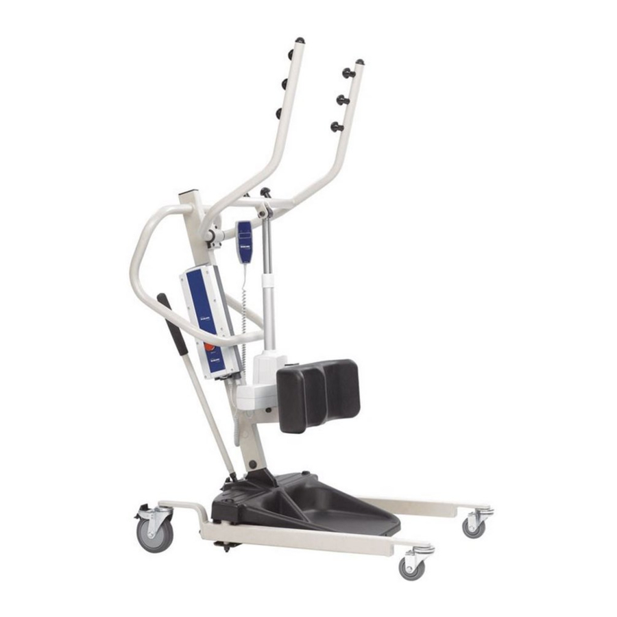
LABEL LOCATION LABEL LOCATION Stand Up Patient Lift Part No. 1078984... -
Page 7: Product Parameters
PRODUCT PARAMETERS PRODUCT PARAMETERS RPS350-1 Stand Up Patient Lift Height at Sling Hook-up - MAX.: 66 inches Height at Sling Hook-up - MIN.: 40 inches Base Width OPEN: 37 inches Base Width CLOSED: 26 inches Base Height (Clearance): 4.5 inches Base Length: 35.5 inches... -
Page 8: Section 1-General Guidelines
SECTION 1—GENERAL GUIDELINES SECTION 1—GENERAL GUIDELINES WARNING SECTION 1 - GENERAL GUIDELINES contains important information for the safe operation and use of this product. Check all parts for shipping damage before using. In case of damage, DO NOT use the equipment. Contact the Dealer for further instructions. The Invacare patient lift is NOT a transport device. It is intended to transfer an individual from one seated surface to another (such as a bed to a wheelchair). DO NOT attempt any transfer without approval of the patient’s physician, nurse or medical assistant. Thoroughly read the instructions in this Owner’s Manual, observe a trained team of experts perform the lifting procedures and then perform the entire lift procedure several times with proper supervision and a capable individual acting as a patient. Invacare Stand Assist and Transfer slings are specifically designed to be used in conjunction with Invacare patient lifts. Slings and accessories designed by other manufacturers are not to be utilized as a component of Invacare’s patient lift system. Use the sling that is recommended by the individual’s doctor, nurse or medical assistant for the comfort and safety of the individual that is being lifted. If the patient lift is used in the area of a shower or bath, ensure that the patient lift is wiped clean of any moisture after use. DO NOT store the lift in a damp area or in a damp condition. Periodically inspect all components of the patient lift for signs of corrosion. Replace all parts that are corroded or damaged. The stand up lift may be operated by one healthcare professional for all lifting preparation, transferring from and transferring to procedures with a cooperative, partial weight‐bearing patient. However, since medical conditions vary, Invacare recommends ... -
Page 9: Operating The Lift
Operating the Lift Make sure there is an audible click when mounting battery on the battery charger to confirm proper mounting. Otherwise, injury or damage may occur. Use the handles to push or pull the patient lift. Lifting the Patient Before positioning the legs of the stand up lift around the patient, make sure that the patient’s feet are out of the way of the foot plate, otherwise injury may occur. Adjustments for safety and comfort should be made before moving the patient. Patientʹs arms should be outside of the sling straps. Before lifting a patient from a stationary object (wheelchair, commode or bed), slightly raise the patient off the stationary object and check that all sling attachments are secure. If any attachment is not correct, lower the patient and correct the problem, then raise the patient and check again. During transfer, with the patient suspended in a sling attached to the lift, DO NOT roll caster base over uneven surfaces that would create an imbalance of the patient lift and could cause the patient lift to tip over. Use steering handle on the mast at ALL times to push or pull the patient lift. Invacare recommends locking the rear swivel casters ONLY when positioning or removing the sling (stand assist or transfer) from around the patient. Invacare does NOT recommend locking of the rear casters of the patient lift when lifting an individual. Doing so could cause the lift to tip and endanger the patient and assistants. Invacare DOES recommend that the rear casters be left unlocked during lifting procedures to allow the patient lift to stabilize itself when the patient is initially lifted from a chair, bed or any stationary object. Transferring the Patient Before transferring, check that the product’s weight capacity can withstand the patientʹs weight. Wheelchair wheel locks MUST be in a locked position before lowering the patient into the wheelchair for transport. Performing Maintenance Regular maintenance of patient lifts and accessories is necessary to assure proper operation. After the first 12 months of operation, inspect all pivot points and fasteners for wear. If the metal is worn, the parts MUST be replaced. Perform this inspection every six months thereafter. DO NOT overtighten mounting hardware. This will damage mounting brackets. Casters and axle bolts require inspections every six months to check for tightness and wear. Part No. 1078984 Stand Up Patient Lift... -
Page 10: Section 2-Assembly
DETAIL “A” to Unlock to Lock WARNING Use only Invacare parts in the assembly of this patient lift. The base legs, the mast, boom, pump assembly and swivel bar are manufactured to Locking specifications that assure correct alignment of all Lever parts for safe functional operation. -
Page 11: Attaching The Battery Charger Mounting Bracket To The Wall
SECTION 2—ASSEMBLY Attaching the Battery Charger Mounting Bracket to the Wall NOTE: For this procedure, refer to FIGURE 2.3. Place the battery charger mounting bracket on the wall at the desired position. With a pencil, mark the middle hole position. Mounting Bracket Measure down 6½ inches from the pencil mark and drill one mounting hole. Install the bottom mounting screw until there is an approximate 1/8‐inch gap between the screw head and Mounting the wall. Screws Put the battery charger mounting bracket onto the bottom mounting screw. Drill the other two mounting holes. Screw the mounting screws through the battery charger mounting bracket and into the wall. Tighten securely. BOTTOM Mounting Screw CAUTION Make sure there is an audible click when mount- ing battery on the battery charger to confirm FIGURE 2.3 Attaching the Battery Charger Mounting Bracket proper mounting. -
Page 12: Section 3- Operation
SECTION 3—OPERATION SECTION 3— OPERATION WARNING DO NOT attempt to transfer a patient without approval of the patient’s physician, nurse, or medical assistant. Thoroughly read the instructions in this owner’s manual, observe a trained team of experts performing the lifting procedures and then perform the entire lift procedure several times with proper supervision and a capable individual acting as a patient. -
Page 13: Activating A Mechanical Emergency Release
NOTE: The lift MUST be under a load for the mechanical release to function. RED Emergency Grip To activate the secondary emergency release, pull up on the RED emergency grip and pull down on the boom at the same time. Charging the Battery NOTE: For this procedure, refer to FIGURE 3.4. NOTE: Invacare recommends the battery be recharged daily to prolong battery life. NOTE: An audible alarm will sound when battery is low. Lift UP on the handle on the back of the battery. Lift the battery up and away from the control box. FIGURE 3.3 Primary Emergency Release CAUTION Battery Make sure there is an audible click when mount- ing battery on the battery charger. Otherwise, Handle injury or damage may occur. -
Page 14: Section 4-Lifting The Patient
ALWAYS keep hands and fingers clear of moving parts to avoid injury. Invacare patient slings are made specifically for use with Invacare patient lifts. For the safety of the patient, DO NOT intermix patient slings and patient lifts of different manufacturers. -
Page 15: Lifting The Patient
Adjustments for safety and comfort should be made before moving the patient. Invacare patient slings are made specifically for use with Invacare patient lifts. For the safety of the patient, DO NOT intermix patient slings and patient lifts of different manufacturers. -
Page 16: Moving The Patient
SECTION 4—LIFTING THE PATIENT WARNING If transferring a patient from a wheelchair, the wheelchair wheel locks MUST be in the locked posi- tion before lowering the patient into the wheelchair. Otherwise, injury may occur. If transferring from a wheelchair, lock the wheel locks on the wheelchair (Detail “B” of FIGURE 4.2). Press the UP arrow button on the hand control to raise the patient above the surface (bed, wheelchair or commode). NOTE: The patient’s weight will be supported by the stand up lift. NOTE: The lower center of gravity provides stability making the patient feel more secure and the lift easier to move. Mast Handle Handgrip Knee Pad DETAIL “A”... -
Page 17: Section 5-Transferring The Patient
Invacare stand up lifts. Otherwise, injury or damage may occur. Invacare does not recommend locking the rear casters of the stand up lift when lifting and transferring an individual. Doing so could cause the lift to tip and endanger the patient and assistants. -
Page 18: Transferring To A Commode Chair
SECTION 5—TRANSFERRING THE PATIENT Transferring to a Commode Chair DETAIL “A” WARNING Invacare recommends locking the rear swivel casters only when positioning or removing the sling from around the patient. NOTE: For this procedure, refer to FIGURE 5.1. Lift the patient from the side of the bed. Press the UP button on the hand control to elevate the patient high enough to clear the arms of the commode chair. Their weight will be supported by the stand up lift. Guide the patient onto the commode chair. This may require two assistants. DETAIL “B”... -
Page 19: Transferring To A Wheelchair
FIGURE 5.2 Transferring to a Wheelchair on the hand control is pressed. Position the patient as far over the bed as possible. NOTE: If patient is being transferred from a surface that is lower than the bed, raise the patient above the surface of the bed. The patient should be elevated just high enough to clear the bed with their weight fully supported by the lift. Press the DOWN button and lower the patient onto the bed. WARNING Invacare recommends locking the rear swivel casters ONLY when positioning or removing the sling from around the patient. Lock the rear swivel casters on the stand up lift. Unhook the sling from all attachment points on the lift. Instruct the patient to lift their feet off of the footplate. Assist the patient if necessary. Remove the standing or transport sling from around the patient. FIGURE 5.3 Transferring to a Bed Unlock the rear swivel casters and pull the lift away from ... -
Page 20: Section 6-Troubleshooting
Refer to Replacing the Electric Actuator on page 23. Lift arms will not lower from the uppermost Lift arms require a minimum Pull down slightly on the lift arms. position. weight load to lower from the uppermost position. NOTE: If problems are not remedied by the suggested means, please contact your dealer or Invacare. Stand Up Patient Lift Part No. 1078984... -
Page 21: Section 7-Maintenance
Whenever necessary. SLINGS CHECK ALL SLING ATTACHMENTS each time it is used to ensure proper connection and patient safety. Inspect sling material for wear. Inspect straps for wear. NOTE: Follow the maintenance procedures described in this manual to keep your patient lift in continuous service. The Invacare Patient Lift is designed to provide a maximum of safe, efficient and satisfactory service with minimum care and maintenance. All parts of the Invacare Lift are made of the best grades of steel, but metal to metal contact will wear after considerable use. There is no adjustment or maintenance of the casters, other than cleaning, lubrication and checking axle and swivel bolts for tightness. Remove all debris, etc. from the wheel and swivel bearings. If any parts are worn, replace these parts IMMEDIATELY. If you question the safety of any part of the lift, contact your Dealer IMMEDIATELY. Cleaning the Sling and the Lift The sling should be washed regularly in water temperature not exceeding 180°F (82°C) and a biological solution. A soft ... -
Page 22: Lubricating The Lift
SECTION 7—MAINTENANCE Lubricating the Lift Square Linkage Rods The Invacare lift is designed for minimum maintenance. However, a six month check and lubrication should ensure continued safety and reliability. Keep lift and slings clean and in good working order. Any defect should be noted and reported to your dealer as soon as possible. The casters MUST swivel and roll smoothly. A light grease (waterproof auto lubricant) may be applied to the ball bearing swivel of the casters once a year. Apply more frequently if the casters are exposed to extreme moist conditions. Linkage Rod Adjusting the Base NOTE: For this procedure, refer to FIGURE 7.1 on page 22. Check the squareness of the legs when in the CLOSED position. Place a square on the inside of the legs and base to determine the 90° alignment. FIGURE 7.1 Adjusting the Base Adjust the linkage rods until 90° alignment is achieved. Adjusting the Knee Pad Height NOTE: For this procedure, refer to FIGURE 7.2. -
Page 23: Replacing The Electric Actuator
SECTION 7—MAINTENANCE Replacing the Electric Actuator Remove the bottom nut, washer and shoulder bolt that secure the electric actuator to the mast mounting bracket. Rest the lift arm on your shoulder and remove the top nut, bolt, bracket and bushing from the lift arm mounting bracket. Remove the electric actuator. Reverse STEPS 1‐3 to install the new electric actuator. WARNING DO NOT overtighten mounting hardware. This will damage mounting brackets. Bracket Bolt Washer Bolt Washer Bushing Bolt Bolt Washer Washer Bushing FIGURE 7.3 Replacing the Electric Actuator Part No. 1078984 Stand Up Patient Lift... -
Page 24: Limited Warranty
For warranty service, please contact the dealer from whom you purchased your Invacare product. In the event you do not receive satisfactory warranty service, please write directly to Invacare at the address on the back cover, provide dealer’s name, address, date of purchase, indicate nature of the defect.
Need help?
Do you have a question about the RPS350-1 and is the answer not in the manual?
Questions and answers