
Related Manuals for intervolt DCC Pro

Summary of Contents for intervolt DCC Pro
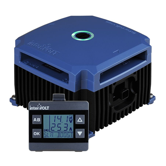
- Page 1 DCC Pro In-Vehicle DC-DC Battery Charger 12VDC 25 AMPS (VERSION R2.0) INSTALLATION & OPERATION MANUAL...
- Page 2 Thank you for choosing an interVOLT product... Intervolt Pty Ltd is a wholly Australian owned and operated private company and the proud owner of the interVOLT brand, a trademark which is registered in over 20 countries worldwide. We have been producing specialised power conversion products for over 15 years.
-
Page 3: Table Of Contents
OVERVIEW .............. 2 Introduction ............2 Outline ..............3 Application.............. 4 Kit Contents............5 FUNDAMENTALS ............ 6 Charging Methods ........... 6 Control Modes ............7 Layout - the Charging Device ........8 Layout - the Remote Display ........9 Standard Wiring Diagram ........10 Wiring using two Charging Devices...... -
Page 4: Overview
Introduction Following its release in 2015 the DCC Pro has enjoyed outstanding success in the overland vehicle market both in Australia and overseas. We are now pleased to introduce version 2.0 which features a number of functionality and performance upgrades o ering even greater ‘value for money’ than the original. -
Page 5: Outline
Our vision for the DCC Pro was a device which would not only provide an autonomous charging method for any auxiliary battery, but would reliably, accurately and repeatedly provide feedback to the operator on the status of the charging and maintenance process. -
Page 6: Application
Application The DCC Pro has been designed speci cally for use in 4WDs, RVs, buses, coaches, caravans, campers or any vehicle with a 12VDC electrical system where there is a requirement to charge one or more secondary (auxiliary) batteries using the starting (main) battery as the primary source. It is not designed or warranted for use in marine applications. -
Page 7: Kit Contents
Kit Contents You have purchased the DCC Pro retail package code number DCC1225ACK-RP. The package contains the components depicted below: DCC Pro Charging Device DCC Pro Remote Display DCC Pro Printed Manual Code: DCC1225ACD Code: DCC0001ARD Code: DCCAUTG1 R2-0 DCC Pro 4mtr Data Cable Code: DCC4000CTR All components are available to purchase separately. -
Page 8: Fundamentals
Charging Methods There are two methods the DCC Pro utilises for charging an auxiliary battery. Although employing the same three stage process for both battery and solar input sources, the methodology is di erent. Both methods can be utilised at the same time thus providing a complete charging solution for your vehicle’s... -
Page 9: Control Modes
Control Modes There are two optional modes which control how the charging system operates. These modes are selectable in the initial set-up process when installing the device and control the charging process in di erent ways. The control modes can always be changed if necessary but the initial set-up and installation steps need to be repeated in order to do so. -
Page 10: Layout - The Charging Device
BATTERY IGNITION POSITIVE CONTROL TERMINAL TERMINAL REMOTE DISPLAY SOLAR OUTPUT PANEL POSITIVE interVOLT Model COMMON TERMINAL DCC1225ACD NEGATIVE Battery to Battery Charging Device TERMINAL 12VDC - 12VDC 25 Amps max. MOUNTING FEET Note: Images above shown approximately half actual size. -
Page 11: Layout - The Remote Display
Layout - Remote Display Front View FOR SWITCHING BETWEEN TWO ‘UP’ SELECTION CHARGING DEVICES. OR HIGH ALSO USED AS BRIGHTNESS BACK AND EXIT CONTROL. BUTTON. ‘DOWN’ SELECTION CONFIRMATION OR LOW SELECTION BUTTON. BRIGHTNESS ALSO USED TO CONTROL. ALSO TOGGLE BETWEEN USED TO TURN OFF DEFAULT AND BACKLIGHT. -
Page 12: Standard Wiring Diagram
Standard Wiring Diagram TO AUXILIARY ENGINE EQUIPMENT FUSE FUSE MAIN OPTIONAL IGNITION SWITCH interVOLT Model DCC1225ACD Battery to Battery Charging Device 12VDC - 12VDC 25 Amps max. CHARGING DEVICE FUSE SOLAR PANEL REMOTE DISPLAY NOTE: Do not connect auxiliary battery to Charging Device... -
Page 13: Wiring Using Two Charging Devices
FUSE FUSE TO AUXILIARY TO AUXILIARY EQUIPMENT EQUIPMENT MAIN FUSE FUSE AUX 1 AUX 2 interVOLT Model interVOLT Model DCC1225ACD DCC1225ACD Battery to Battery Battery to Battery Charging Device Charging Device 12VDC - 12VDC 12VDC - 12VDC 25 Amps max. -
Page 14: Installation
For example if the DCC Pro is required to charge a battery in a caravan it may be better to mount the Charging Device in the caravan itself rather than the vehicle but this may depend on where the Remote Display needs to be located. -
Page 15: Installation Essentials
Furthermore, this can result in safety issues such as breakdowns and in worst case scenarios even re. This is why we state that the DCC Pro should only be installed by a suitably quali ed tradesperson. -
Page 16: Installing The Charging Device
Installing the Charging Device The DCC Pro Charging Device has been designed to cope with demanding conditions and can be installed in the vehicle’s engine compartment. Care must be taken when performing the installation to ensure performance, longevity and of course, safety. Installing the device too close to a turbocharger for example may not only force the device into thermal shut down but could also result in catastrophic failure. -
Page 17: Installing The Data Cable
Installing the Data Cable The Data Cable is the communication link between the Charging Device and the Remote Display. It has a sealed connection at the device end and unsealed connector at the display end. If the Charging Device is installed in the engine bay, a 10mm diameter feed-through hole must be drilled in the rewall for the Data Cable. -
Page 18: Installing The Remote Display
Installing the Remote Display The DCC Remote Display is designed to be installed in the cabin of the vehicle, on the dash or console. It should be shielded from excessive heat and located away from direct sunlight if possible. A user adjustable ball joint allows for the housing to swivel through a range of positions to best suit the operator. -
Page 19: Wiring The Charging Device
POWER TERMINATION IGNITION TERMINATION The DCC Pro is fully protected electronically against catastrophic failure. It is mandatory however that inline fuses are tted to protect the wiring in the event of an external short circuit. The fuse rating should not be less than the continuous current rating of the wiring. -
Page 20: Connection And Configuration
Connection and Configuration A step-by-step guide In some applications, the DCC Pro can be installed and connected straight out of the box without any changes to the con guration. In other situations it is necessary to change these defaults, a di erent battery type for example, as detailed below (see Charging Methods section on page 6 for explanation). -
Page 21: Installation Steps
Important! Please read before attempting any connection • All steps must be completed in the order indicated. Do not connect the auxiliary battery cable until step 13. For safety reasons there are speci c settings that are locked out once the auxiliary battery is connected. - Page 22 Connect the other end of the negative to the main battery negative (recommended) or directly to the chassis, ensuring the connection has good contact. Ensure the auxiliary interVOLT Model DCC1225ACD Battery to Battery battery negative is either connected to Charging Device...
- Page 23 Configure the Charging Device: Initialising set-up mode This step need only be done if changing the factory default settings Con guring or ‘setting up’ the Charging Device is the next step in the sequence. To initiate set-up mode follow the steps below: I.
- Page 24 Configure the Charging Device: Ignition control mode Following the last step (9) con rm if you want to enable ignition control mode. Use the scroll buttons to select one of the two following options: I. To disable ignition mode select OFF II.
-
Page 25: Operation
Connect the Charging Device end of the positive cable to the terminal marked AUX using the special screw provided. Connect the other end of the cable to the auxiliary interVOLT Model battery positive. Insert the fuse into the DCC1225ACD Battery to Battery... - Page 26 Reinstall the terminal cover Locate the terminal cover according to the arrows. The cover is indexed and must t into the locating pins in order for the Glow Ring to operate correctly. The installation is now complete, however if you have a second Charging Device to install please proceed to step 18.
-
Page 27: Operating Brief
Operating Brief The DCC Pro is a fully self-contained Charging Device for in-vehicle battery to battery charging. The kit is supplied complete with the Remote Display and the Data Cable however, aside from initial programming of the operating mode and battery type, it is not essential to use the Remote Display if not required. - Page 28 This indicator is located on the top (terminal cover) of the Charging Device. The LED Glow Ring is an integral part of the DCC Pro’s control and monitoring system, changing colour and state according to the status of the Charging Device. Please see page 32 for detailed...
-
Page 29: Operator Control And Monitoring
Operator Control and Monitoring Once installed and con gured the DCC Pro Remote Display can be used to monitor a range of functions and provide valuable feedback to the operator on the status of the dual battery system. Display-On-Demand At any time the Charging Device is in stand by mode the Remote Display can be ‘woken’... - Page 30 Backlight On/O Control By default the backlight is always on when powered but it can be switched o at any time by pressing and holding button for 2 seconds. It can be switched on again by pushing either the button momentarily. Toggle Alternate Screen By default, the lower three digit character set will display the current in Amps or, if solar power is in use, the...
- Page 31 When battery to battery charging, the Remote Display will indicate the following by default: • Auxiliary Charging Voltage. This is displayed in Volts using the upper character set. • Auxiliary Charging Current. This is displayed in Amps using the lower character set. •...
-
Page 32: Operator Convenience Settings
Operator Convenience Settings The Remote Display also allows certain changes to be made at any time or ‘on the y’ . There are three options which can be con gured for operator convenience details as follows; 1) Option 1: The keypad beeper. This option simply turns the keypad beeper, also known as ‘button clicks’... - Page 33 3) Option 3: The backlight brightness. This option allows the operator to adjust the backlight brightness for both high (H i ) and low (Lo) settings to enable the ‘one touch’ operation of both. Each setting allows the brightness to be adjusted over 5 increments. In H i setting, the range is 0 through 5 with 5 being the maximum and in Lo, 0 through -5 with -5 being the minimum.
-
Page 34: System Status
To assist with troubleshooting any problems that arise, the DCC Pro can indicate these issues in one of two ways, via the Charging Device itself or on the Remote Display (if connected). -
Page 35: Troubleshooting
Alert Conditions There are certain conditions that may arise in operation that could result in an alert condition. In an alert condition the output of the Charging Device will be automatically disabled and the alert symbol will be displayed (if the Remote Display is on). -
Page 36: Error Conditions
Error Conditions In addition there are certain conditions which may result as a communication issue between the Charging Device and Remote Display. These will be displayed in the form of a System Error on the Remote Display in one of four ways, details as follows: SYS 1 –... -
Page 37: Frequently Asked Questions
Wait 1 minute before pressing the button again. Why do I get a system error when I try to re-programme the DCC Pro? Disconnect both batteries then re-connect the main battery only. Press and hold the button until you hear the audible beep. -
Page 38: Specifications
Input Voltage Main 9 – 16 VDC Solar 18 – 28 VOC (open circuit Voltage – no load) Solar Power Unrestricted (system limited to 25 Amps) Continuous Rating 25 Amps@50°C (de-rate from 50°C to 85°C) Current Draw Charging Device In stand by: Including LED indicator <10mA At full load: Up to 35 Amps Remote Display With backlight off: 10mA max... - Page 39 DCC Pro Charging Device Length Width Height 112mm 112mm 75mm Footprint Mounting Centres 95mm x 95mm DCC Pro Remote Display Length Width Height 60mm 36mm 59mm...
-
Page 40: Appendix
Fundamentals in Detail CHARGING FUNCTIONS Soft start: This function is the initial phase of the boost/CC stage cycle. In soft start the current is allowed to build gradually, e ectively controlling the high inrush current normally experienced at ‘switch on’ . Controlling the inrush current reduces the risk of further damage if the battery is unserviceable and prevents potential issues with any equipment that may be powered from the battery at the time. - Page 41 . In this mode the DCC Pro has two optional settings. These settings allow the DCC Pro to be used in traditional vehicles with conventional charging methods or the new ECU controlled systems used in modern design.
- Page 42 In order to prevent further damage due to overcharging, the DCC Pro is programmed for the safest option which is to reduce the Voltage by switching out of constant current mode into oat stage. There is also the possibility that a heavy load permanently connected to the auxiliary battery is responsible for the charging cycle to time out in boost/CC stage before terminal Voltage is achieved.
-
Page 43: Warranty Policy
24 months against faulty materials and/or workmanship from date of purchase by the end user subject to proof of purchase. In the event proof of purchase is not provided, and at the discretion of the manufacturer, the warranty shall be 24 months from manufacturer’s date of sale to... - Page 44 Manufactured by Intervolt Pty Ltd interVOLT is a registered trademark of Amelec Australia Pty Ltd in Australia and various other countries including the UK and USA and as such is protected by the relevant laws of the country of registration.
Need help?
Do you have a question about the DCC Pro and is the answer not in the manual?
Questions and answers