
Related Manuals for intervolt DCC Pro

Summary of Contents for intervolt DCC Pro
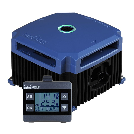
- Page 1 DCC Pro In-Vehicle DC-DC Battery Charger 12VDC 25 AMPS INSTALLATION & OPERATION MANUAL...
- Page 2 There are several features and bene ts which set the DCC Pro apart from the current o erings on the market. An introduction to the unique and innovative DCC Pro can be found on the Overview page in this manual.
-
Page 3: Table Of Contents
OVERVIEW .............. 2 Introduction ............2 Kit Contents............3 Application.............. 4 Synopsis..............5 FUNDAMENTALS ............ 6 Charging Modes ............6 Charging Methods ........... 7 Layout - the Charging Device ........8 Layout - the Remote Display ........9 Standard Wiring Diagram ........10 Wiring using two Charging Devices...... -
Page 4: Overview
As a concept our vision for the DCC Pro was a device which would not only provide an autonomous charging method for any auxiliary battery, but would reliably, accurately and repeatedly provide feedback to the operator on the status of the charging and maintenance process. -
Page 5: Kit Contents
Kit Contents You have purchased the DCC Pro retail package code number DCC1225ACK-RP. The package contains the components depicted below: DCC Pro Remote Display DCC Pro Printed Manual DCC Pro Charging Device Code: DCC1225ACD Code: DCC0001ARD Code: DCCAUTG1 R1-0 DCC Pro 3mtr Data Cable... -
Page 6: Application
Application The DCC Pro is a solid state electronic device developed for the purpose of charging and maintaining an additional battery (or batteries), commonly termed an auxiliary battery in a dual or multiple battery installation where the main battery is used as the supply source. -
Page 7: Synopsis
(MPPT) to capitalise on any available solar power and optimise the charging process. With ability to be voltage or ignition controlled, the DCC Pro has the exibility to adapt to almost any application. Furthermore, the ignition control function allows for selection of normal or low ignition input to cater for traditional or ECU controlled electrical systems. -
Page 8: Fundamentals
Charging Modes There are two optional modes which control how the charging system operates. These modes are selectable in the initial set-up process when installing the device and control the charging process in di erent ways. The control modes can always be changed if necessary but the initial set-up and installation steps need to be repeated in order to do so. -
Page 9: Charging Methods
The battery to battery charging method can be controlled by either voltage or ignition mode as outlined previously. The DCC Pro is referred to as a three stage charger meaning there are three stages or cycles the device progresses through to achieve optimal charging of an auxiliary battery. -
Page 10: Layout - The Charging Device
BATTERY IGNITION POSITIVE CONTROL TERMINAL TERMINAL REMOTE DISPLAY SOLAR OUTPUT PANEL POSITIVE interVOLT Model COMMON TERMINAL DCC1225ACD NEGATIVE Battery to Battery Charging Device TERMINAL 12VDC - 12VDC 25 Amps max. MOUNTING FEET Note: Images above shown approximately half actual size. -
Page 11: Layout - The Remote Display
Layout - Remote Display Front View FOR SWITCHING BETWEEN TWO ‘UP’ SELECTION CHARGING DEVICES. OR HIGH ALSO USED AS BRIGHTNESS BACK AND EXIT CONTROL. BUTTON. ‘DOWN’ SELECTION CONFIRMATION OR LOW SELECTION BUTTON. BRIGHTNESS ALSO USED TO CONTROL. ALSO SWITCH BETWEEN USED TO TURN OFF AUXILIARY AND BACKLIGHT. -
Page 12: Standard Wiring Diagram
Standard Wiring Diagram TO AUXILIARY ENGINE EQUIPMENT FUSE FUSE MAIN OPTIONAL IGNITION SWITCH interVOLT Model DCC1225ACD Battery to Battery Charging Device 12VDC - 12VDC 25 Amps max. FUSE SOLAR PANEL DCC DISPLAY... -
Page 13: Wiring Using Two Charging Devices
AUX 1 AUX 2 interVOLT Model interVOLT Model DCC1225ACD DCC1225ACD Battery to Battery Battery to Battery Charging Device Charging Device 12VDC - 12VDC 12VDC - 12VDC 25 Amps max. 25 Amps max. DCC PRO B DCC PRO A DCC DISPLAY... -
Page 14: Installation
For example if the DCC Pro is required to charge a battery in a caravan it may be better to mount the Charging Device in the caravan itself rather than the vehicle but this may depend on where the Remote Display needs to be located. -
Page 15: Installing The Charging Device
Installing the Charging Device The DCC Pro Charging Device has been designed to cope with arduous conditions and can be installed in the vehicle’s engine compartment. Care must be taken when performing the installation to ensure performance, longevity and of course, safety. Installing the device too close to a turbocharger for example may not only force the device into thermal shut down but could also result in catastrophic failure. -
Page 16: Wiring The Charging Device
Wiring the Charging Device In a standard installation, the Charging Device should be wired according to the schematic on page 10. A standard installation consists of a Charging Device and Remote Display. If two Charging Devices are being installed please see page 11 for the alternate schematic. -
Page 17: Installing The Data Cable
Installing the Data Cable The Data Cable is the communication link between the Charging Device and the Remote Display. It has a sealed connection at the device end and unsealed connector at the display end. The Data Cable is tted with a PVC ‘clamshell’ protector over the Remote Display connector plug. -
Page 18: Installing The Remote Display
Installing the Remote Display The DCC Remote Display is designed to be installed in the cabin of the vehicle, on the dash or console. It should be shielded from excessive heat and located away from direct sunlight if possible. The Remote Display is made up of two main sub-assemblies, the display housing itself and the mounting base. -
Page 19: Connection And Configuration
Connection and Configuration A step-by-step guide In some applications, the DCC Pro can be installed and connected straight out of the box without any changes to the con guration. In other situations it is necessary to change these defaults, a di erent battery type for example, as detailed below (see Charging Modes section on page 6 for explanation). -
Page 20: Installation Steps
Connect the other end of the negative to the main battery negative (recommended) or directly to the chassis, ensuring the connection has good contact. Ensure the auxiliary interVOLT Model DCC1225ACD Battery to Battery battery negative is either connected to Charging Device... - Page 21 MAIN using the special screw provided. Connect the other end of the cable to the main battery positive. Insert the fuse into the inline fuse holder. The interVOLT Model DCC1225ACD Battery to Battery Charging Device is now powered and...
- Page 22 Configure the Charging Device: Selecting battery type Following the last step (6) above the message ‘BATT TYPE’ will appear. To select the auxiliary battery type, follow the steps below: I. Press the button to enter the battery type selection menu. II.
- Page 23 Connect the Charging Device end of the positive cable to the terminal marked AUX using the special screw provided. Connect the other end of the cable to the auxiliary interVOLT Model battery positive. Insert the fuse into the DCC1225ACD Battery to Battery...
-
Page 24: Operation
See pages 6-7 for more information. As a result the LED indicators will re ect the current stage, for example if the current interVOLT Model stage is ‘ oat’ they will illuminate green DCC1225ACD Battery to Battery continuously. - Page 25 Unplugging the Data Cable from the Charging Device. Using a pair of needle nose pliers, apply a little pressure to the sides of the Data Cable plug and gently withdraw the plug assembly. As pressure is applied to the plug the locking tab momentarily deforms and is released from the mating recess.
-
Page 26: Operating Brief
Operating Brief The DCC Pro is a fully self-contained charging device for in-vehicle battery to battery charging. The kit is supplied complete with the Remote Display and the Data Cable however, aside from initial programming of the operating mode and battery type, it is not essential to use the Remote Display if not required. - Page 27 This indicator is located on the top (terminal cover) of the Charging Device. The LED Glow Ring is an integral part of the DCC Pro’s control and monitoring system, changing colour and state according to the status of the Charging Device. Please see page 31 for detailed...
-
Page 28: Operator Convenience Settings
Operator Convenience Settings The Remote Display also allows certain changes to be made at any time or ‘on the y’ . There are three options which can be con gured for operator convenience details as follows; 1) Option 1: The keypad beeper. This option simply turns the keypad beeper, also known as ‘button clicks’... - Page 29 3) Option 3: The backlight brightness. This option allows the operator to adjust the backlight brightness for both high (HI) and low (Lo) settings to enable the ‘one touch’ operation of both. Each setting allows the brightness to be adjusted over 5 increments. In HI setting, the range is 0 through 5 with 5 being the maximum and in Lo, 0 through -5 with -5 being the minimum.
-
Page 30: Operator Control Functions
Operator Control Functions Backlight Brightness Control Once the backlight brightness settings have been selected (see page 27), controlling it becomes a convenient one touch process. Press the button momentarily and the backlight will assume the highest pre-set brightness Press the button momentarily and the backlight will assume the lowest pre-set brightness Backlight On/O Control... -
Page 31: Operator Monitoring Functions
Operator Monitoring Functions Once installed and con gured the DCC Pro Remote Display can be used to monitor a range of functions and provide valuable feedback to the operator on the status of the dual battery system. The Battery Icon is a multi-function indicator used to display the di erent charging cycles and methods. - Page 32 When battery to battery charging, the Remote Display will indicate the following: • Auxiliary Charging Voltage. This will always be displayed as the upper character set. • Auxiliary Charging Current. This is displayed by default as the lower character set but can be toggled using the button to display the Main Battery Voltage.
-
Page 33: System Status
To assist with troubleshooting any problems that arise, the DCC Pro can indicate these issues in one of two ways, via the Charging Device itself or on the Remote Display (if connected). -
Page 34: Alert Conditions
Alert Conditions There are certain conditions that may arise in operation that could result in an alert condition. In an alert condition the output of the Charging Device will be automatically disabled and the alert symbol will be displayed. A message indicating the cause of the condition will be displayed on the multi-function character set. -
Page 35: Error Conditions
Error Conditions In addition there are certain conditions which may result as a communication issue between the Charging Device and Remote Display. These will be displayed in the form of a System Error on the Remote Display in one of four ways, details as follows: SYS 1 –... -
Page 36: Specifications
Input Voltage Main 9 – 17 VDC Solar 27 VOC max. (open circuit – no load) Solar Power 250 Watts nominal (300 Watts peak) Continuous Rating 25 Amps @ 50°C Current Draw Charging Device Including LED indicator <10mA (in standby) Remote Display With backlight off: 10mA max With backlight on: 30mA max... - Page 37 DCC Pro Charging Device Length Width Height 112mm 112mm 75mm Footprint Mounting Centres 95mm x 95mm DCC Pro Remote Display Length Width Height 60mm 36mm 59mm...
-
Page 38: Appendix
Fundamentals in Detail CHARGING FUNCTIONS Soft start: This function is the initial phase of the boost stage cycle. In soft start the current is allowed to build gradually over time, e ectively controlling the high inrush current normally experienced at ‘switch on’ . Controlling the inrush current reduces the risk of further damage if the battery is unserviceable and prevents potential issues with any equipment that may be powered from the battery at the time. - Page 39 NORMAL and LOW settings and is set to 12.5V (remember this is the voltage level of the main battery). In order to conserve power, the DCC Pro will NOT commence charging, even with the ignition ON if the main battery has a voltage level below 12.5V.
- Page 40 In order to prevent further damage due to overcharging, the DCC Pro is programmed for the safest option which is to reduce the voltage by switching out of constant current mode into oat stage. There is also the possibility that a heavy load permanently connected to the auxiliary battery is responsible for the charging cycle to time out in boost stage before terminal voltage is achieved.
- Page 41 Watts and display the text SLT SOLAR. Scenario 2: The main battery voltage is above 12.8V and the DCC Pro is in a normal charging cycle (boost, absorption or oat).
- Page 42 When the main battery is fully charged (exceeds pre-determined maximum alternator voltage) it will then be released and the DCC Pro will continue to charge the auxiliary battery as long as required or until solar power is no longer available. In this mode the LED Glow Ring will indicate aqua green continuously.
-
Page 43: Warranty Policy
24 months against faulty materials and/or workmanship from date of purchase by the end user subject to proof of purchase. In the event proof of purchase is not provided, and at the discretion of the manufacturer, the warranty shall be 24 months from manufacturer’s date of sale to... - Page 44 Amelec Australia Pty Ltd in Australia and various other countries including the UK and USA and as such is protected by the relevant laws of the country of registration. © 2015. All rights reserved. The entire contents of this instruction manual shall remain the property of Amelec Australia Pty Ltd and should not be reproduced without written permission.
Need help?
Do you have a question about the DCC Pro and is the answer not in the manual?
Questions and answers