Strong Razor Series Instruction Manual
Articulating versamount
Hide thumbs
Also See for Strong Razor Series:
- Installation manual (12 pages) ,
- Installation manual (4 pages) ,
- Installation manual (4 pages)
Advertisement
Quick Links
Advertisement

Subscribe to Our Youtube Channel
Related Manuals for Strong Strong Razor Series


Summary of Contents for Strong Strong Razor Series
- Page 1 SM-VM-ART1-IW-L Strong™ Razor Series Articulating VersaMount INSTRUCTION MANUAL...
-
Page 2: Tools Required
Warnings • Installation of this product should be done by a qualified professional. • Do not begin installation before reviewing and understanding these instructions. • E nsure the mounting wall used can safely support 4 times the combined weight of the mount and chosen display. • Under no circumstances should this product be mounted to metal studs. • The manufacturer does not accept responsibility for incorrect installation. This wall mount is intended for use only with the maximum weight CAUTION: of 75 lbs./34 kg. Use with heavier than the maximum weight indicated may result in instability causing possible injury. Tools Required •... - Page 3 Hardware Bag 1 (A) Phillips Head (B) Phillips Head (C) Phillips Head (D) Phillips Head Machine Screw, Machine Screw, Machine Screw, Machine Screw, M4x10 (4) M4x20 (4) M4x30 (4) M5x10 (4) (E) Phillips Head (F) Phillips Head (G) Small Nylon Spacer, (H) M5 Washer, Machine Screw, Machine Screw, OD12xID5.5x5 (8) M5x12x1 (16) M5x20 (4) M5x30 (4) Bag 2 (I) Phillips Head (J) Phillips Head (K) M6 Lock Nut (8) (L) M6 Washer Machine Screw, Machine Screw, M6X16X1.5 (8) M6x10 (4) M6x16 (8) (M) Phillips Head (N) Phillips Head (O) Phillips Head (P) Phillips Head Machine Screw, Machine Screw, Machine Screw, Machine Screw, M6x20 (4)
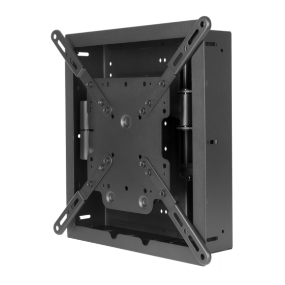
- Page 4 Overview Thank you for purchasing a great product from Strong™. We appreciate your purchase and are committed to providing the highest quality products possible. The Strong VersaMount™ is designed to provide the best in-wall TV-mounting solution for installers adding equipment behind low-profile displays and other wall-mounted equipment. It can easily be installed in new jobs with the included dust cover to protect the VersaMount™ during construction. Inside the enclosure, components may be mounted using the built-in attachment points with expansion pins or zip ties. Add a wattbox (not included) to the bottom of the VersaMount™ for the best power and space-saving solution. Installing Equipment into the Strong VersaMount™ The VersaMount allows for a variety of equipment configuration options. Experiment with the equipment configuration to determine the best installation method. For images of different configurations of equipment installed in the VersaMount, see the VersaMount product page and Support Tab at www.SnapAV.com. Using Knockouts The knockouts on the top and bottom of the VersaMount may be used for installing low voltage rings or for outlet boxes. If an outlet box is installed, it must be an old work, residential grade box with integrated work supports to allow for secure mounting.
- Page 5 Old Work Installation Instructions 1. M ark the desired height of the top of the SM-VM-ART1-IW-L on the wall between two stud centers. Use a stud finder to locate the stud locations. Use the cut-out template to mark the wall, using a level to line it up correctly. Carefully cut the opening using a drywall saw. A fter the hole is cut, test fit the box, and clean up the opening as needed. I nsert the box into the opening. Using a #1 Phillips screwdriver, secure the box to the studs with 2 lag bolts located on both sides of the box.
- Page 6 Install the Display Adapter Plate Figure 1. A. C arefully lay the display face-down on a soft surface. B. L ocate the four mounting holes in the back of the display housing. Try to thread screws (A through N) in until the correct thread is found for the holes. C. L ay the adapter plate over the holes in the display (directional arrow facing up), and check the clearance between the TV and the plate. Make sure the mounting holes match up properly to four of the holes in the...
- Page 7 11. Detaching the Arm Assembly from the Enclosure Note: It is not recommended to remove the Arm Assembly from the enclosure, but you may if so desired by carefully following the instructions below. A. Loosen the two upper clamping screws on the arm assemble, and loosen the 2 lower screws. B. Remove the upper, middle screw from the lower left corner of the rear of the VersaBox panel. Note: Do not reinstall this screw if you wish to remove the arm after the VersaMount has been installed in the wall, as you will no longer have access to this screw. C. Pull the mount arm up and away from the can to detach the mount. Untighten Screws Untighten...
- Page 8 13. Adjusting Display Position 13.1 Horizontal Level Adjustments 1. L oosen the two locking nuts (W) at the bottom of the arm assembly end plate using the 8mm socket wrench (T3). (Figure 11) Place a level on top of the display, and rotate the display until it is horizontally level. (Figure 12) Tighten the locking nuts at the bottom of the arm assembly end plate and then loosen them ¼ turn. This will allow for the display to be positioned with minimal effort. After adjustment is complete, tighten the nuts.
- Page 9 13.3 Adjusting Home Position (Fully Retracted) The mount includes a home position latch that secures the arm Figure 15. to the wall mount. This prevents the display from being pushed (Y) x1 away from the wall due to cabling. (Z) x3 Note: Only the TV Plate side of the latch is pre-installed. The home position latch clip requires installation and adjustment.
- Page 10 14. Notes Pg. 10...
- Page 11 www.snapav.com Support: (866) 838-5052 Pg. 11...
-
Page 12: Warranty
Warranty Limited Lifetime Warranty All Strong back-boxes and brackets have a Lifetime Limited Warranty. This warranty includes parts and labor repairs on all Lifetime components found to be defective in material or workmanship under normal conditions of use. This warranty shall not apply to products that have been abused, modified, or disassembled.
Need help?
Do you have a question about the Strong Razor Series and is the answer not in the manual?
Questions and answers