
Subscribe to Our Youtube Channel
Related Manuals for Strong Strong VersaMount SM-VM-ART2-IW-XL


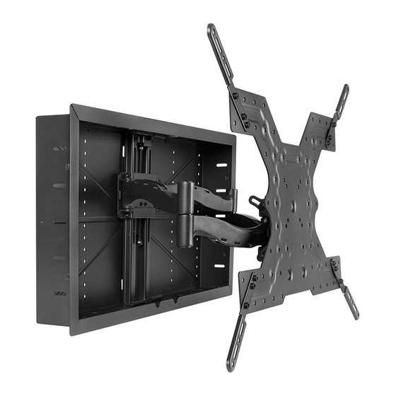
Summary of Contents for Strong Strong VersaMount SM-VM-ART2-IW-XL
- Page 1 SM-VM-ART2-IW-XL Strong™ VersaMount™ Dual-Arm In-Wall Articulating Mount SM-VM-ART2-IW-XL INSTALLATION MANUAL...
- Page 2 WARNINGS • These wall mounts are intended for use only with the maximum weight capacities listed below. • Installation by a qualified professional is highly recommended for this product. • Do not begin installation until you thoroughly read and understanding these instructions. • Ensure the mounting wall will safely support four times the combined weight of the mount and display panel. •...
- Page 3 HARDWARE IMAGE DESCRIPTION ITEM BAG 1 Lag Bolt (A) 6 × 40 mm Lag Bolt (B) 8 × 40 mm Screw (C) M6 × 20 mm Screw (D) M6 × 40 mm Screw (E) M8 × 20 mm Screw (F) M8 × 40 mm BAG 2 Screw (G) M8 ×...
-
Page 4: Additional Tools Required
CAUTION: This wall mount is intended for use only with a maximum display weight of 100 lb / 45 kg. Exceeding the maximum weight may result in instability causing damage and possible injury. WARNING: Wood studs must be a minimum of 2”×4”. Additional Tools Required •... - Page 5 Installing the Header and Footer Brackets 16" O.C. Materials required: - Brackets - 12 Wood Screws (S) - Level - Wood Shims (if needed) - Power drill w/ 1/8" bit Insert the footer bracket into the wall. • Use a level to align the bracket. Using the angle braces at either side of the center stud, drill 1/8"...
- Page 6 • Drive Lag Bolts (B) through holes to secure the vertical track to wood frame. NOTE: Lags will go through holes on vertical track and enclosure and be secured into wood braces built from step 5. Installing Equipment into the Strong VersaMount knockouts The VersaMount allows for a variety of equipment options.
- Page 7 Install the Display Adapter Plate This mount is compatible with most VESA patterns between 75×75 and 800×600. Some VESA ³ ³ patterns require the use of the included display adapter brackets. The table at right shows whether ³ ³ ³ your display requires adapter brackets: standard ³...
- Page 8 10. Attach the Display to the Arm Assembly • Lift the display and place the bolt at the center of the plate into the notch as shown. Once placed, the two bolts at the bottom will swing into place through the level adjustment slots. •...
- Page 9 11.2 Vertical Position Adjustments WARNING: Loosen the vertical shift lock bolts before adjusting the vertical position. Using vertical shift while lock screws are engaged will damage the height adjustment system. • Locate the four locking bolts on the sides of the vertical track. Loosen these bolts so the sled can move up and down. There are two on each side, all four must be disengaged before adjusting height.
-
Page 10: Attach Bezel
11.3 Tilt Adjustments Tilt adjustments usually do not require loosening any bolts or screws. The tilt plate fasteners have been pre-adjusted for easy adjustment with most TVs. However, heavier TVs may sag due to the extra weight. Manually adjust the display to your preferred angle, then evenly tighten the lock nuts on each side of the arms using the 10mm socket wrench to prevent the display from sagging. - Page 11 13. Dimensions All dimensions in INCHES. 25.27 31.50 24.84 23.62 31.34 20.81 30.25 21.23 31.34 29.06 Pg. 11...
- Page 12 Wirepath Home Systems, LLC, dba “Control4” and/or dba “SnapAV” in the United States and/or other countries. Control4, Snap AV, Strong, Strong Versabox, and WattBox are also registered trademarks or trademarks of Wirepath Home Systems, LLC. Other names and brands may be claimed as the property of their respective owners. All specifications subject to change without notice.
Need help?
Do you have a question about the Strong VersaMount SM-VM-ART2-IW-XL and is the answer not in the manual?
Questions and answers