
Related Manuals for Strong Contractor Series


Summary of Contents for Strong Contractor Series
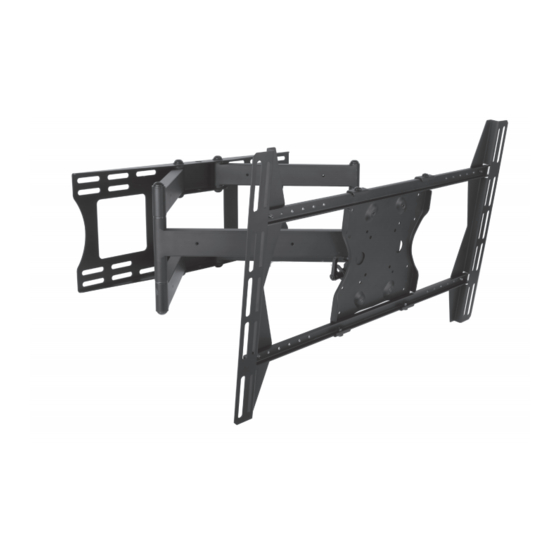
- Page 1 SM-CS-ART2-L SM-CS-ART2-XL Strong™ Contractor Series Universal Articulating Mount With Dual Arms INSTALLATION MANUAL...
- Page 2 WARNING The maximum weight of this wall mount is 150 lbs (68.04 kg). Use with heavier than the maximum weight indicated may result in instability causing possible injury. Ensure these instructions are thoroughly understood before attempting installation. If unsure of any part of the installation process, contact a professional installer for assistance.
- Page 3 INSTALLATION Layout and Drilling Determine general location of the display. Use a stud finder to find the nearest wall studs if applicable and mark their location. Tape template flat and level to wall surface, aligning the template’s slots with the stud markings on the wall. NOTE: Use of a bead level is recommended.
- Page 4 Assemble Display Bracket Slide the Adapter Brackets onto each end of the Adapter Rods (Figure 2). Adapter Rod Adapter Bracket Adapter Plate Bolts (AA) Figure 2 Mount Display Bracket to Display Panel Place the assembled Display Bracket on the back of the display with one Adapter Bracket aligned with a set of vertical mounting holes (Figure 3).
- Page 5 Attach Screen to Arm Assembly Insert two bolts (BB) into top two holes of Adapter Plate. Leave approximately 1/4" of exposed thread (do not fully tighten). Lift the display and hook the two bolts (BB) in grooves on top of the Mounting Head (Figure 4). Insert two bolts (BB) in bottom two holes of the Mounting Head, securing it to the Adapter Plate.
- Page 6 ADJUSTMENTS Tilt Adjustment Loosen Tilt Levers on each side of mount head (only enough to allow controlled adjustment) (Figure 6). Adjust tilt. Tighten locking Tilt Levers. NOTE: Once the tilt levers are locked, the position of the levers can be adjusted without loosening or tightening the unit by pulling the levers outward and then repositioning them to a vertical, less obtrusive position.
- Page 7 Phone: (866) 838-5052 Email: techsupport@snapav.com LIFETIME LIMITED WARRANTY Strong™ Mounts have a Lifetime Limited Warranty. This warranty includes parts and labor repairs on all components found to be defective in material or workmanship under normal conditions of Lifetime use. This warranty shall not apply to products which have been abused, modified or disassembled.
- Page 8 150120_2300 © 2015 STRONG...
Need help?
Do you have a question about the Contractor Series and is the answer not in the manual?
Questions and answers