Strong Razor Series Installation Manual
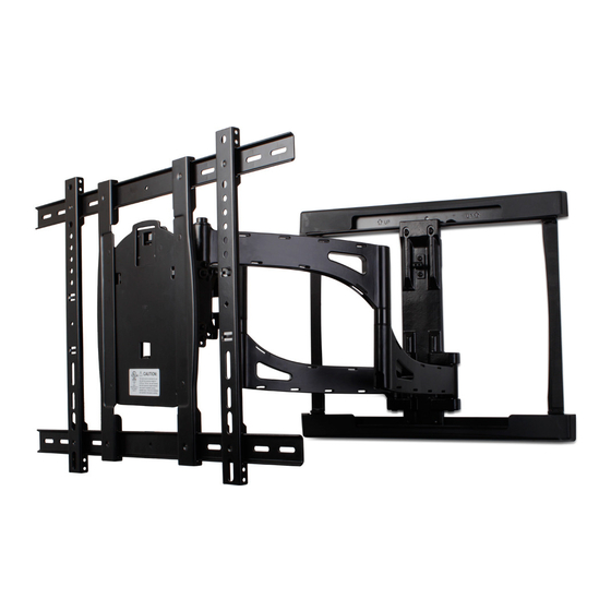
Articulating mount for large and extra large displays
Hide thumbs
Also See for Razor Series:
- Instruction manual (12 pages) ,
- Installation manual (4 pages) ,
- Installation manual (4 pages)

Subscribe to Our Youtube Channel
Related Manuals for Strong Razor Series


Summary of Contents for Strong Razor Series
- Page 1 SM-RAZOR-ART2-L / SM-RAZOR-ART2-XL Strong™ Razor Series Articulating Mount for Large and Extra Large Displays INSTALLATION MANUAL...
- Page 2 Installation Manual pg.2 © 2015 Strong...
-
Page 3: Specifications
Installation Manual Warnings: • Installation of this product should be done by a qualified professional. • Do not begin installation before reviewing and understanding these instructions. • Ensure the mounting wall used can safely support 4 times the combined weight of the mount and chosen display. • The manufacturer does not accept responsibility for incorrect installation. CAUTION: This wall mount is intended for use only with the maximum weight of 100lbs/45.35 kg. - Page 4 (AD) S10 Socket (AE) S8 Socket Key (1) Key (1) Wrench (1) Wrench (1) Bag 5 Bag 6 (XL Only) (AH) Latching (AF) Extension (AI) M5x8 bolts (2) (AG) machine Clip (1) brackets (4) screw, M5x6 (16) pg.4 © 2015 Strong...
-
Page 5: Installation
Installation Manual Installation Step 1. Pre-Drill Wall for Mounting A. For Mounting on a Stud Wall A-1. Place the Wall Plate on the wall in the desired position for the display. A-2. Mark the mounting hole locations over the wall studs. A-3. - Page 6 Once the Arm Assembly is secured, the Wall Bracket End Covers can be installed to the top and bottom of the Wall Bracket. Figure 5 Figure 6 Mounting Block Top Step 3B (Pull Down to fit onto rail) Adjustment Screws Figure 7 Mounting Mounting Block (AA) Hardware Step 3A pg.6 © 2015 Strong...
- Page 7 Installation Manual Step 4. Attach TV Plate to Display Figure 8A With the orientation marking (Up Arrow) towards the top of the TV, place the TV Plate on the back of display aligning the upright bars with the mounting holes on the display. (Figure 8A) If the holes do not align: B-1.
- Page 8 D. Tighten the 4 Lock Nuts on the rear of the Arm Plate using the S10 Socket Wrench (AD). (Figure 14) Retract the Arm if necessary. Note: Right Arm Not Shown to Expose Lock Nut Position pg.8 © 2015 Strong...
-
Page 9: Step 9. Tilt Adjustments
Installation Manual Step 8. Adjusting Home Position (Fully Retracted) The mount includes a Home Position Latch which locks the Arm to the Wall Mount to avoid the display being pushed away from the wall by cabling. Figure 15A Note: Only the TV Plate side of the latch is pre-installed, the Home Position Latch clip requires installation, and adjustment. -
Page 10: Step 10. Wire Management
(Figure 17) Additionally, wires can be zip tied to the clips on the vertical bars of the TV bracket. (Figure 18) Figure 18 Wire Wire Clips Dimensions 25.50 9.32 18.55 8.18 1.60 17.50 20.31 pg.10 © 2015 Strong... -
Page 11: Lifetime Limited Warranty
Installation Manual Lifetime Limited Warranty Strong™ Mounts have a Lifetime Limited Warranty. This warranty includes parts and labor repairs on Lifetime all components found to be defective in material or workmanship under normal conditions of use. This warranty shall not apply to products which have been abused, modified or disassembled. Products to be repaired under this warranty must be returned to SnapAV or a designated service center with prior notification and an assigned return authorization (RA) number. - Page 12 © 2015 STRONG™ 150325-2207...
Need help?
Do you have a question about the Razor Series and is the answer not in the manual?
Questions and answers