Lantronix xPico 200 Series User Manual
Hide thumbs
Also See for xPico 200 Series:
- Certification firmware instructions (21 pages) ,
- Manual (7 pages)
Advertisement
xPico 200 Series Evaluation Kit User Guide
This guide describes how to setup the xPico® 200 series evaluation kit and provides the
information needed to evaluate the included xPico 240 or xPico 250 embedded gateway
modules. The intended audience is the engineers that design the xPico 200 into their
products.
Evaluation Kit Contents
Lantronix® xPico® 200 series allows OEMs to go to market faster with their smart
connected products. It delivers seamless and secure Ethernet, Wi-Fi and/or Bluetooth®
connectivity. Featuring advanced enterprise security, complete Wi-Fi®, network and
Bluetooth stack offload, essential applications for data connectivity and control, pre-
integration with the MACH10™ platform, the xPico 200 series delivers embedded
gateway capability in an industry-leading compact footprint.
Advertisement
Table of Contents

Related Manuals for Lantronix xPico 200 Series


Summary of Contents for Lantronix xPico 200 Series
- Page 1 The intended audience is the engineers that design the xPico 200 into their products. Evaluation Kit Contents Lantronix® xPico® 200 series allows OEMs to go to market faster with their smart connected products. It delivers seamless and secure Ethernet, Wi-Fi and/or Bluetooth® connectivity. Featuring advanced enterprise security, complete Wi-Fi®, network and Bluetooth stack offload, essential applications for data connectivity and control, pre- integration with the MACH10™...
-
Page 2: Evaluation Kit Description
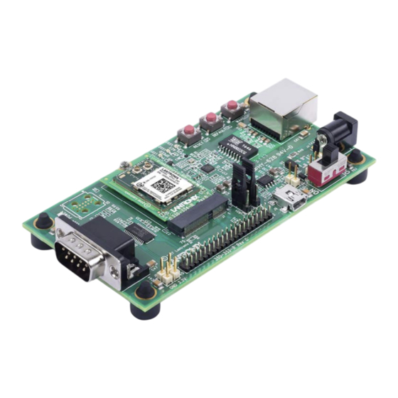
The evaluation kit is available in two different variants depending on xPico 200 series model that is mounted: 1. XPC240300EK - xPico 240 module (Ethernet + Wi-Fi) 2. XPC250300EK - xPico 250 module (Ethernet + Wi-Fi + Bluetooth) Evaluation Kit Contents: xPico 200 module (xPico 240 or xPico 250 model) on an edge card ... - Page 3 xPico 200 Evaluation Board Connectors, Headers and Switches Ref Des. Connector/Header Functions xPico 200 Module Socket 3.3V Power Header Test point to monitor the 3.3V regulator output. Ground Header Test point to connect to evaluation board signal ground. USB Host/Device Select Install Jumper to pins 1 to 2 for USB Device Mode Install Jumper to pins 2 to 3 for USB Host Mode (Host mode also requires jumper install on JP5, JP6 to provide power out of J9)
- Page 4 Ref Des. Connector/Header Functions SDIO Master/Slave Select Install Jumper pins 1 to 2 for SDIO Master Mode Install Jumper pins 2 to 3 for SDIO Slave Mode USB Host Power Out Jumper Install to provide power out for USB host mode. Do not install for device mode (default) USB Host Power Out Jumper Install to provide power out for USB host mode.
-
Page 5: Serial Interface
Serial Interface The evaluation kit has one RS232 port for connection to the xPico 200 internal UART. Serial port 1 is a DB9M (DTE) connector labeled J6. The null modem cable can be used to connect J6 directly to a standard PC RS232 serial port. RS‐232 Signals on J6 Serial Interface xPico 200 Evaluation Kit DB9M... -
Page 6: Power Supply
LED Function Design xPico 200 Status LED blinks with patterns indicating module status. See the LED1 Orange xPico 200 Series Embedded Wi-Fi Gateway User Guide a full description of the status LED blink patterns. Ethernet Link Status None LED2 Orange... - Page 7 LED Ref Color LED Function Design 3.3V Power LED None LED4 Blue LED is ON when evaluation board 3.3V power is up. J2 Header Pins J2 Pin Header table lists the pin functionality of the additional evaluation kit headers. Included is the J7 connection to the xPico 200 edge module connector. J2 Pin Header J7 module J2 Header...
- Page 8 J7 module J2 Header Secondary Signal Function Function Configurable pin 4 SPI MOSI Configurable pin 5 I2C Data Configurable pin 6 I2C clock Configurable pin 7 SPI Clock Configurable pin 8 SPI Chip Select SDCLK SDIO Clock SDCMD SDIO Command SDIO0 SDIO Data 0 SDIO1...
- Page 9 UART clear to CTS1 send input 23, 25, 31, Reserved-Do not connect connect Please refer to the xPico 200 Series Embedded Wi-Fi Gateway Integration Guide evaluation board schematics. Buttons Button Signal Module Button Function Module Hardware Reset EXT_RESET# Button assertion reboots the module...
-
Page 10: Additional Information
Additional Information Intellectual Property Lantronix and xPico are registered trademarks of Lantronix, Inc. in the United States and other countries. Patented: http://patents.lantronix.com; additional patents pending. Warranty For details on the Lantronix warranty policy, please go to our Web site at https://www.lantronix.com/support/warranty. -
Page 11: Additional Documentation
Lantronix Web Manager, CLI, XML and Guide WebAPI. xPico 200 Provides information needed to integrate the xPico 200 series gateway into Series customer-printed circuit boards. This includes instructions for connecting Integration various module pin function groups, and general module placement and Guide mounting. -
Page 12: Technical Support
For regular updates to Lantronix documentation and to receive product change notifications, register at the Lantronix homepage. Technical Support Lantronix Technical Support offers many resources to support our customers and products. For instance, ask a question, find firmware downloads, access the FTP site and search through tutorials, FAQs, bulletins, warranty information, extended support services, and product documentation.
Need help?
Do you have a question about the xPico 200 Series and is the answer not in the manual?
Questions and answers