Lantronix xPico 110 User Manual
Wired device server module evaluation kit
Hide thumbs
Also See for xPico 110:
- Quick start manual (3 pages) ,
- Integration manual (34 pages) ,
- Quick start manual (2 pages)
Table of Contents
Advertisement
Quick Links
Chipsmall Limited consists of a professional team with an average of over 10 year of expertise in the distribution
of electronic components. Based in Hongkong, we have already established firm and mutual-benefit business
relationships with customers from,Europe,America and south Asia,supplying obsolete and hard-to-find components
to meet their specific needs.
With the principle of "Quality Parts,Customers Priority,Honest Operation,and Considerate Service",our business
mainly focus on the distribution of electronic components. Line cards we deal with include
Microchip,ALPS,ROHM,Xilinx,Pulse,ON,Everlight and Freescale. Main products comprise
IC,Modules,Potentiometer,IC Socket,Relay,Connector.Our parts cover such applications as commercial,industrial,
and automotives areas.
We are looking forward to setting up business relationship with you and hope to provide you with the best service
and solution. Let us make a better world for our industry!
Contact us
Tel: +86-755-8981 8866 Fax: +86-755-8427 6832
Email & Skype: info@chipsmall.com Web: www.chipsmall.com
Address: A1208, Overseas Decoration Building, #122 Zhenhua RD., Futian, Shenzhen, China
Advertisement
Table of Contents

Subscribe to Our Youtube Channel
Related Manuals for Lantronix xPico 110


Summary of Contents for Lantronix xPico 110
- Page 1 Chipsmall Limited consists of a professional team with an average of over 10 year of expertise in the distribution of electronic components. Based in Hongkong, we have already established firm and mutual-benefit business relationships with customers from,Europe,America and south Asia,supplying obsolete and hard-to-find components to meet their specific needs.
- Page 2 xPico Wired Device Server Module Evaluation Kit User Guide Part Number 900-788-R Revision A April 2017...
-
Page 3: Intellectual Property
Technical Support Online: www.lantronix.com/support Sales Offices For a current list of our domestic and international sales offices go to the Lantronix web site at www.lantronix.com/about/contact. Disclaimer and Revisions Note: This product has been designed to comply with the limits for a Class B digital device pursuant to Part 15 of FCC and EN55032 Rules when properly enclosed and grounded. -
Page 4: Revision History
Revision History Date Rev. Comments April 2017 Initial document. xPico® 110 Wired Device Server Module Evaluation Kit User Guide... -
Page 5: Table Of Contents
About this Guide ___________________________________________________________ 6 Additional Documentation ____________________________________________________ 6 2: Evaluation Kit xPico 110 Evaluation Kit Contents _____________________________________________ 7 xPico 110 Evaluation Kit Description ____________________________________________ 7 Serial Port 1 RS232/RS485 and Serial Port 2 RS232 Interface ______________________ 10 Ethernet Port _____________________________________________________________ 14... -
Page 6: List Of Figures
List of Figures Figure 2-1 xPico 110 Evaluation Kit XPW100100K-01 Connectors and Jumpers __________ 8 Figure 2-2 JP8, JP9, and JP17 Headers _______________________________________ 13 List of Tables Table 2-1 Evaluation Kit Connectors, Header and Switches _________________________ 9 Table 2-2 RS-232 Signals on J3 Serial Port _____________________________________ 11... -
Page 7: 1: Introduction
Introduction About this Guide This guide provides the information needed to use the Lantronix® xPico® 110 Device Server with the evaluation kit. The intended audience is the engineers that design the xPico 110 into their products. Notes: All the Hardware and Firmware required to evaluate the xPico 110 turnkey application are provided in the Evaluation Kit. -
Page 8: 2: Evaluation Kit
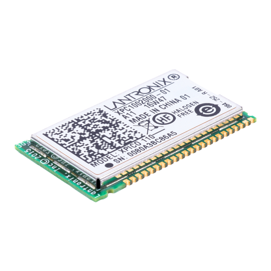
Evaluation Kit The xPico 110 evaluation kit helps you get familiar with your xPico 110 wired device server so that you may understand how to integrate it into a given product design. xPico 110 Evaluation Kit Contents ♦ xPico 110 Module ♦... -
Page 9: Figure 2-1 Xpico 110 Evaluation Kit Xpw100100K-01 Connectors And Jumpers
2: Evaluation Kit Figure 2-1 xPico 110 Evaluation Kit XPW100100K-01 Connectors and Jumpers xPico® 110 Wired Device Server Module Evaluation Kit User Guide... -
Page 10: Table 2-1 Evaluation Kit Connectors, Header And Switches
110 Module PCB Pads 76-pin castellation pads. Note: The evaluation kit comes with an xPico 110 already soldered onto the board, and is ready for testing. WARNING: If you need to replace or install a new xPico 110 sample onto the evaluation... -
Page 11: Serial Port 1 Rs232/Rs485 And Serial Port 2 Rs232 Interface
8 CPs Provides access to xPico 110 module configurable pins CP9 to CP16 Module Reset to Default When pushed and hold for a defined period, the xPico 110 module resets to factory default function. Module Hardware Reset When pushed, the XPico 110 module resets (same as power cycle reset) Board Power Switch Switch to turn ON/OFF external power input at JP19. -
Page 12: Table 2-2 Rs-232 Signals On J3 Serial Port
2: Evaluation Kit Table 2-2 RS-232 Signals on J3 Serial Port xPico 110 Evaluation Kit PIN FUNCTION DB9M SERIAL PORTS Pin # TX_232 (Data Out) RX_232 (Data In) CTS_232 (HW Flow Control Input) RTS_232 (HW Flow Control Output) DTR_232 (Modem Control Output) -
Page 13: Table 2-6 Jp18 Serial Port 2 Rs232 Connections (Cable-Side Signals)
2: Evaluation Kit Table 2-6 JP18 Serial Port 2 RS232 Connections (cable-side signals) xPico Evaluation Kit Serial Port 2 JP18 pin TX RS232 output Signal Ground RX RS232 input Jumper headers JP17, JP8 and JP9 have been included to allow for each of the serial port signals to be connected or disconnected from the serial port transceiver. -
Page 14: Figure 2-2 Jp8, Jp9, And Jp17 Headers
2: Evaluation Kit Figure 2-2 JP8, JP9, and JP17 Headers xPico® 110 Wired Device Server Module Evaluation Kit User Guide... -
Page 15: Ethernet Port
2: Evaluation Kit Ethernet Port The xPico 110 evaluation kit includes one RJ45 connector with on-board magnetics for connection to the xPico 110 module 10/100Mbps Ethernet interface. Connector J2 is the Ethernet port. Power Supply The evaluation kit provides several options for input power. Included with the kit is a 5V wall adapter. -
Page 16: Leds
LED Function Design option LED1 Hardwired Orange xPico 110 Status LED blinks with patterns indicating module status. See the xPico 110 user guide for a full description of the status LED blink patterns. LED2 JP10 Orange Ethernet Link Status LED is ON when there is a valid Ethernet link... -
Page 17: Additional Headers
JP21 pin 7 CP15, configurable pin Test point JP21 pin 8 CP16, configurable pin Test point Note: Please refer to the xPico 110 Wired Device Server Integration Guide for evaluation board schematics. xPico® 110 Wired Device Server Module Evaluation Kit User Guide...
Need help?
Do you have a question about the xPico 110 and is the answer not in the manual?
Questions and answers