
Subscribe to Our Youtube Channel
Related Manuals for SKF HTL201 EEX


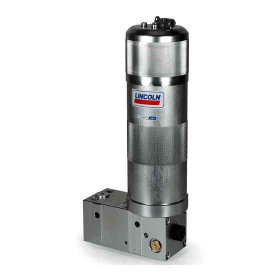
Summary of Contents for SKF HTL201 EEX
- Page 1 Operating Instructions Hydraulically driven lubrication pump following ATEX directive 2014/34/EU HTL201 EEX 951-181-016-EN 2016/12/21 Version 03...
-
Page 2: Eu Declaration Of Conformity Following Atex Directive 2014/34/Eu
EU Declaration of conformity EU Declaration of conformity following ATEX directive 2014/34/EU, annex X The manufacturer, SKF Lubrication Systems Germany GmbH, Walldorf Facilities, Heinrich-Hertz-Str. 2-8, DE - 69190 Walldorf hereby declares that the apparatus Designation: Hydraulically driven pump to supply lubricants... -
Page 3: Legal Disclosure
Fax: +49 (0) 6227 33-259 product All rights reserved. ○ intent or negligence Berlin Facilities Motzener Straße 35/37 ○ use of non-original SKF spare parts. Warranty 12277 Berlin The instructions do not contain any informa- Liability for loss or damage resulting from Germany tion on the warranty. -
Page 4: Table Of Contents
Table of contents Table of contents EU Declaration of conformity following ATEX directive 2014/34/EU ....2 1.19 Initial commissioning / daily start-up ..........15 Legal disclosure ...................... 3 1.20 Cleaning ....................15 Explanation of symbols, signs and abbreviations ..........6 1.21 Special safety instructions regarding explosion protection .....16 1.22 Expiry of the ATEX approval ..............17 Safety instructions .............. - Page 5 Disposal ....................50 Equipotential bonding ................35 Adjusting the output volume ...............36 Spare parts................. 51 Filling with lubricant ................37 14.1 Pump HTL201 EEX assy..............51 Venting of the pump ................38 14.2 Lubricant reservoir assy...............51 Emergency lubrication .................39 14.3 Pressure control valve ................52 6.10...
-
Page 6: Explanation Of Symbols, Signs And Abbreviations
Explanation of symbols, signs and abbreviations Explanation of symbols, signs and abbreviations The following abbreviations may be used within these instructions. Symbols within safety notes mark the kind and source of the hazard. General warning Dangerous electrical voltage Risk of falling Hot surfaces Unintentional intake Crushing hazard... - Page 7 Explanation of symbols, signs and abbreviations Abbreviations and conversion factors regarding °C degrees Celsius °F degrees Fahrenheit approx. approximately Kelvin Ounce i.e. that is Newton fl. oz. fluid ounce etc. et cetera hour inch poss. possibly second pounds per square inch if appl.
-
Page 8: Safety Instructions
1. Safety instructions 1. Safety instructions 1.2 General behaviour when handling the 1.1 General safety instructions ○ Safety-related protective and emergency product ○ The owner must ensure that safety infor- devices must not be removed, modified ○ The product may be used only in aware- or affected otherwise in their function mation has been read by any persons en- ness of the potential dangers, in proper... -
Page 9: Intended Use
1. Safety instructions 1.3 Intended use 1.5 Painting ○ to supply, transport, or store hazardous ○ The pump is delivered in unpainted Supply of lubricants within a centralized lu- substances and mixtures in accordance brication system following the specifications, condition and can be operated without with annex I part 2-5 of the CLP regula- technical data and limits stated in these painting. -
Page 10: Notes Related To The Ce Marking
1. Safety instructions 1.7 Modiications of the product 1.6 Notes related to the CE marking 1.9 Inspections prior to delivery CE marking is effected following the require- The following inspections were carried out Unauthorized conversions or modifica- prior to delivery: ments of the applied directives: tions may result in unforeseeable impacts ○... -
Page 11: Markings On The Product
Instructions. reservoir Model: ________________________________ Warning of hot surfaces. P. No. ________________________________ Series ________________________________ Wear suitable eye protection SKF Lubrication Systems Germany GmbH Model: HTL-K7-1,5XF EEX P.No.: 642-41184-9 II 2G c II C TX I M2 c II 2D c TX -25 °C... -
Page 12: Persons Authorized To Operate The Pump
1. Safety instructions 1.14 Brieing of external technicians 1.13 Persons authorized to operate the 1.13.4 Specialist for maintenance and pump repairs in potentially explosive Prior to commencing the activities, external atmospheres technicians must be informed by the opera- 1.13.1 Operator A person who is qualified by training, know- tor of the company safety provisions, the ledge and experience to identify and assess... -
Page 13: Operation
1. Safety instructions ○ Ensure through suitable measures that 1.16 Operation 1.18 Transport, installation, maintenance, malfunctions, repair, shutdown, movable or detached parts are immobi- The following must be observed during lized during the work and that no limbs disposal. commissioning and operation. can be caught in between by inadvertent ○... - Page 14 1. Safety instructions ○ Ensure proper grounding of the product. ○ Observe the specified tightening torques. ○ All components used must be designed When tightening, use a calibrated torque for: ○ Ensure proper connection of the protec- wrench. - maximum operating pressure tive earth conductor.
-
Page 15: Initial Commissioning / Daily Start-Up
1. Safety instructions 1.19 Initial commissioning / daily start-up 1.20 Cleaning ○ Risk of fire and explosion when using Ensure that: inflammable cleaning agents. Only use ○ All safety devices are completely available non-flammable cleaning agents suitable and functional for the purpose. ○... -
Page 16: Special Safety Instructions Regarding Explosion Protection
1. Safety instructions 1.21 Special safety instructions regarding explosion protection ○ The ignition temperature of the hydraulic ○ Always behave so that explosion hazards The repairs are to be marked by a repair oil must lie at least 50 K over the maxi- are avoided. -
Page 17: Expiry Of The Atex Approval
○ Avoid dust accumulation and remove ○ Use of non-original with by the user. dust immediately. Dust accumulations SKF spare parts ○ Information on explosion protection have a thermally insulating effect and, if ○ Non-observance of these instructions according to directive 1999/92/EC whirled up, generate the formation of a and other applicable documents. -
Page 18: Operator Obligations
1. Safety instructions 1.25 Operator obligations 1.25.3 Provision of necessary information The operator ○ documents the measures for explosion The operator must make the instructions required for the respective activity accessible 1.25.1 Determination of hazards protection. to all people commissioned with operation, The operator must determine all hazards re- ○... -
Page 19: Instruction And Qualification Obligations
1. Safety instructions 1.25.4 Instruction and qualiication obligations The operator clearly determines the respon- ○ dealing with lubricants and cleaning sibility of personnel for operation, instal- agents. lation and repairs. The operator is obliged ○ use and inspection of personal protective to instruct all people authorized for use in equipment, where appropriate the correct handling of the machine prior to... -
Page 20: General Residual Risks
1. Safety instructions 1.26 General residual risks Residual risk Possible in life cycle Remedy Personal injury/ material damage Keep unauthorized persons away. No people may remain under suspended loads. Lift parts A B C G H K due to falling of raised parts with adequate lifting devices. -
Page 21: Residual Risks Atex
2.Lubricants 1.27 Residual risks ATEX Residual risk Remedy Usage in a potentially explosive atmosphere with- ○ Check the equipotential bonding with regard to electrical continuity before the initial start-up, out testing the equipotential bonding with regard after each repair and additionally at regular intervals to be determined by the operator. to electrical continuity ○... - Page 22 2. Lubricants Residual risk Remedy ○ Secure parts against falling. Where appropriate, cover parts in order to avoid the formation of Generation of electrostatic charges and sparks through dropping parts. sparks. ○ Ensure that none of these substances gets into the potentially explosive area. Have all substances Bringing catalytic, unstable or pyrophoric substances into a potentially explosive area approved by the operator.
-
Page 23: Lubricants
2.2 Selection of lubricants 2.3 Material compatibility Lubricants are used specifically for certain SKF considers lubricants to be an element Lubricants must generally be compatible application purposes. In order to fulfil their of system design. A suitable lubricant is se-... -
Page 24: Lubricants In Explosive Atmospheres
It is possible for lubricants to be tested in the company's laboratory for their suitability for being pumped in centralized lubrication sys- tems (e.g. "bleeding"). Please contact SKF. if you have further ques- tions regarding lubricants. You may request an overview of the lubri- cants tested by SKF. -
Page 25: Overview, Functional Description
3. Overview, functional description 3. Overview, functional description Overview Fig. 1 1 Reservoir The reservoir with a follower piston resting on the lubricant stores the lubricant. 1.1 Reservoir venting device The reservoir vent (1.1) is positioned on the reservoir. It provides air for the reservoir while the pump is operating and consuming lubri- cant and vents the reservoir when it is filled with lubricant. - Page 26 3. Overview, functional description Overview Fig. 2 5 Vent screw Serves to vent the lubricant. To do so, after filling the reservoir the vent screw (5) must be loosened there leaks a small amount of lubri- cant. Then firmly tighten the vent screw again. 6 Filler fitting The filler fitting serves to fill the reservoir via a transfer pump.
- Page 27 3. Overview, functional description Overview Fig. 3 11 Pressure control valve The pressure control valve (11) protects the pump and the lubrication system components against too high pressure. The pressure con- trol valve is set to 270 bar. 12 Equipotential bonding connection The equipotential bonding connection is lo- cated on the bottom of the pump.
-
Page 28: Technical Data
4. Technical data 4. Technical data 4.1 Mechanics Product version 642-41184-9 Operating temperature range of the pump -25 °C to +65 °C The indicated operating temperature range of the pump presupposes the suitability of the lubricant used for the actually existing operating tem- perature. -
Page 29: Nominal Output Volumes
4. Technical data 4.2 Nominal output volumes Pump element Nominal output per stroke 0.22 cc This information applies for greases of NLGI class 2 at 40 °C and 100 bar counterpressure and the hydraulic operating pressure indicated in the diagram. Out- put volumes can be increased or reduced by turning the throttle into the plus or minus direction. -
Page 30: Tightening Torques
4. Technical data 4.3 Tightening torques Adhere to the stated tightening torques. Pos. Component Tightening torque Pump element with integrated check valve 25 Nm ± 2.0 Nm Emergency lubrication fitting 14 Nm ± 1.0 Nm Vent screw 3 Nm ± 0.1 Nm Filler fitting 14 Nm ±... -
Page 31: Delivery, Returns, And Storage
This particularly applies for parts made out of plastic and rubber (embrittlement) as well 5.3 Storage as for components primed with SKF products are subject to the following lubricant (ageing). storage conditions: ○ dry, dust- and vibration-free in closed premises ○... -
Page 32: Installation
6. Installation 6. Installation 6.1 General information Protect the product against humidity and During assembly and particularly during Only qualified technical personnel may in- vibration and install it in an easily accessible any drilling work always pay attention to the stall, operate, maintain, and repair the prod- position to ensure all other installations can following:... -
Page 33: Mechanical Connection
6. Installation 6.2 Mechanical connection Minimum assembly dimensions Fig. 4 6.2.1 Minimum assembly dimensions Ensure sufficient space for maintenance work or for a possible disassembly of the product by leaving a free space of at least 100 mm into each direction in addition to the stated dimensions. -
Page 34: Installation Bores
(14) made of steel exceeding the diameter of the lubricant res- ervoir (1). The distance piece (14) can not be ordered from SKF. The free space for the pressure control valve (11), predetermined by the two distance holders of the pump housing, must be maintained. -
Page 35: Hydraulic Lines
6. Installation 6.3 Hydraulic lines Hydraulic lines and equipotential bonding Fig. 6 Use suitable hydraulic fittings and lines to connect the pump with the pressure con- nection P (8) and the return-line connection T (10) to the hydraulic circuit of the superior machine / the carrier system. -
Page 36: Adjusting The Output Volume
6. Installation 6.6 Adjusting the output volume Adjusting of the output volume Fig. 7 During pump operation the output volume must never be changed. The pump is factory-set to maximum output. • Switch off the hydraulic system of the su- perior machine or carrier system. -
Page 37: Filling With Lubricant
6. Installation 6.7 Filling with lubricant Filling with lubricant Fig. 8 WARNING Risk of explosion Only fill lubricant reservoir, if the transfer pump is connected to the equipotential bonding of the su- perior machine or if no explosive atmosphere is present. Personal injury When filling the pump wear suitable face protection and gloves. -
Page 38: Venting Of The Pump
6. Installation 6.8 Venting of the pump Venting of the pump Fig. 9 Vent the pump after each filling of the reser- voir. By doing so a possible functional failure of the pump due to air inclusions can be avoided. During the reservoir filling pro- cedure the vent screw must not be open. -
Page 39: Emergency Lubrication
6. Installation 6.9 Emergency lubrication Emergency lubrication via emergency lubrication fitting Fig. 10 WARNING Risk of explosion Carry out emergency lubrication only, if the transfer pump is con- nected to the equipotential bonding of the superior machine or if no ex- plosive atmosphere is present. -
Page 40: Lubrication Line Connection
6. Installation 6.10 Lubrication line connection ○ The lubricant flow should not be impeded Observe the following installation instruc- CAUTION tions for safe and smooth operation. by the installation of sharp elbows, angle valves, gaskets protruding to the inside, ○ Use clean components and primed lubri- Risk of falling or cross-section changes (big to small). -
Page 41: Initial Start-Up
7. Initial start-up 7. Initial start-up In order to warrant safety and function, a person assigned by the operator must carry out the following inspections. Immediately eliminate detected deficiencies. Deficiencies may be remedied by an authorized and qualified specialist only. Start-up check list 7.1 Inspections prior to initial start-up Mechanical connections carried out correctly... -
Page 42: Operation
8. Operation 8. Operation SKF products operate automatically to the greatest possible extent. Basically, activities during standard opera- tion are limited to: ○ Filling with lubricant (chapter 6.7) ○ Venting after filling with lubricant (chapter 6.8) ○ Cleaning / replacing the oil strainer (chapter 10.1) -
Page 43: Cleaning
• Thorough cleaning of all outer surfaces uct will be required. Thoroughly remove residues of with a damp cloth. To do so, contact the SKF Customer Service. cleaning agents from the product and rinse off with clear water. Make sure to keep the reser-... -
Page 44: Maintenance
10. Maintenance Maintenance Regular and appropriate maintenance is a prerequisite to detect and clear faults in time. The specific timelines have to be determined, verified at regular intervals and adapted, if necessary, by the operator based on the operating conditions. If needed, copy the table for regular maintenance activities. Maintenance check list Activity to be done Mechanical connections carried out correctly... -
Page 45: Clean Or Replace Oil Strainer
11. Faults 10.1 Clean or replace oil strainer Clean or replace oil strainer Fig. 11 The oil strainer must be cleaned or replaced every 1,000 operat- ing hours. • Switch off the hydraulic system of the superior machine • Remove fitting of hydraulic connection P •... -
Page 46: Troubleshooting
11. Faults Troubleshooting Fault table 2 Fault Possible cause Remedy ○ Hydraulic system of carrier device is switched off ○ Switch the hydraulic system on ○ Pressure in the hydraulic system is too low (< 80 bar) ○ Check the hydraulic system ○... -
Page 47: Repairs
12. Repairs Repairs 12.1 Replacing the pressure control valve Replace pressure control valve Fig. 12 WARNING To reach the pressure control Risk of injury valve, depending on the side of Before carrying out any repair work, attachment of the pump, it may take at least the following safety be necessary to disassemble the measures:... -
Page 48: Replacing The Reservoir
13. Shutdown and disposal 12.2 Replacing the reservoir Replace reservoir Fig. 13 Reservoir should be empty when replacing it. When removing the reservoir, the lubricant inside will leak. To replace the reservoir proceed as follows: • Use e.g. strap wrench to loosen the res- ervoir anticlockwise. - Page 49 13. Shutdown and disposal Replace reservoir Fig. 13 • Take the flat packing (16) out of the con- nection adapter (17). • Check flat packing (16) for damages and replace by a new flat packing in case of damage. • Insert the flat packing (16) into the con- nection adapter (17) again.
-
Page 50: Shutdown And Disposal
13. Shutdown and disposal Shutdown and disposal 13.1 Temporary shutdown 13.3 Disposal Temporarily shut the system down by: Countries within the European Union ○ switching off the superior machine. Parts made of plastic or metal Disposal should be avoided or minimized 13.2 Final shutdown and disassembly wherever possible. -
Page 51: Spare Parts
14. Spare parts Spare parts The spare parts assemblies may be used exclusively for replacement of identical defective parts. Modifications with spare parts on existing products are not allowed. 14.1 Pump HTL201 EEX assy. Fig. 14 Designation Qty. Part number Pump HTL201-K7-1,5 XF EEX assy. -
Page 52: Pressure Control Valve
14. Spare parts 14.3 Pressure control valve Fig. 16 Designation Qty. Part number Pressure control valve (270 bar) 235-14343-2 14.4 Oil strainer Fig. 17 Designation Qty. Part number Strainer screw G1/4 x 17 100 μm 447-72394-1 14.5 Closure screw Fig. 18 Designation Qty. -
Page 53: Filler Fitting
14. Connection diagrams 14.6 Filler itting Fig. 19 Designation Qty. Part number Hydraulic lubrication fitting ST BR 1/8 Z 251-14045-1 14.7 Emergency lubrication itting Fig. 20 Designation Qty. Part number Emergency lubrication fitting +RV A2 AR 1/8 251-14073-9 14.8 Flat packing Fig. - Page 54 A global presence provides SKF customers uniform quality standards and worldwide product availability. Important information on product usage All products from SKF may be used only for their intended purpose as described in this brochure and any instructions. 951-181-016-EN Not all lubricants are suitable for use in centralized lubrication systems.
Need help?
Do you have a question about the HTL201 EEX and is the answer not in the manual?
Questions and answers