
Related Manuals for SKF LINCOLN FlowMaster II C Series


Summary of Contents for SKF LINCOLN FlowMaster II C Series
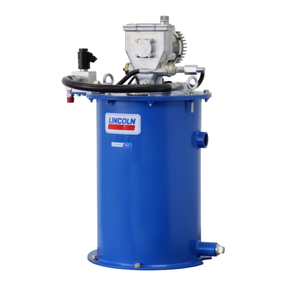
- Page 1 User and maintenance instructions FlowMaster II rotary driven electric pump (24 V Model 482-2532*, series “C”, CAT branded* Date of issue August 2021 Form number 404696 Version * Indicates change.
-
Page 2: Table Of Contents
Contents Explanation of Safety safety signals Read and carefully observe installation instructions before installing, operating or Explanation of safety signals troubleshooting referenced equipment. NOTE Safety Equipment must be installed, maintained Emphasizes useful hints and System specifications ....2 recommendations as well as information for and repaired exclusively by efficient and trouble-free operation. -
Page 3: Overview
Install pump Overview Maintenance and repair Model 482-2532* is a FlowMaster II rotary Locate unit so that electric power connection driven pumping unit designed to operate is accessible. a Centro-Matic lubrication system. General maintenance The pump includes motor speed control 1 Mark center locations of six holes at and built in circuit protection to prevent bottom of reservoir. -
Page 4: Outlet Check Service
Outlet check service Fig 1 Outlet check assembly (5) Refer to Fig 1. The pump will not build up sufficient lubricant pressure if the outlet check assembly (5) is fouled. Foreign material may lodge beneath steel ball (47) or between check bushing assembly (44) and seat of pump check disc assembly (43). -
Page 5: Follower
Follower Fig 2 Follower assembly (24) Refer to Fig 2 and Fig IPB 1, page 9. Service unit if follower foam is damaged or fails to wipe sides of reservoir effectively. 1 Remove bolts (17) and lock washers (18) attaching the cover to the reservoir. 2 Lift the entire pump, vent valve and cover assembly out of the reservoir. -
Page 6: Fill Reservoir With Optional 278552 Bypass Manifold Assembly
Fill reservoir with optional NOTE NOTE 278552 bypass manifold For ease of filling tank, pressure relief valve or Do not fill reservoir until grease level drops at pressure regulator (not provided) can be least 1 in (25 mm). assembly mounted remotely. Refer to Fig 4 for proper connection of 1 Lock out and tag out electrical systems. -
Page 7: Float Switch
Float switch Fig 6 Fig 7 Float switch (8) Float switch (8) consists of a normally open dry contact switch at top and a series of reed switches below, Fig 6. Dry contact switch controls a full indicator light or alarm. Reed switches control a level gauge displaying reservoir level in ten percent increments. -
Page 8: Mechanical Shut-Off Valve
Fig 8 Mechanical shut-off valve, block and guide assembly (70) All ports are in NPTF. Apply two drops of 242 Loctite, 180° apart. Torque to 30–35 ft-lbf (41–47 Nm). Mechanical shut-off valve Mechanical shut-off valve automatically shuts off filling of reservoir without power applied to system. -
Page 9: Individual Parts Breakdown
Fig IPB 1 9, 10 Ø 15- / in Ø 13- / in (384 mm) (352 mm) / in (447 mm) Ø / in (12,7 mm) Mounting 40° / in holes (x 6) 20° (490 mm) 33, 34 Torque to 33, 34 9-10 ft.lbf (12-13,5 Nm) -
Page 10: Service Parts
Service Parts Item no. Description Qty. Part no. Item no. Description Qty. Part no. Extension tube 276853 Gasket 31001 Hose 272711 Steel ball ( 66001 Adapter 12989 Outlet connector 90860 Adapter 12213 Gasket 274540 Outlet check assembly 81938 Float magnet 274543 90°... -
Page 11: Troubleshooting
Troubleshooting Condition Possible cause Corrective action Pump does not operate. No electrical power to pump. Turn on or connect 24 V power. Motor relay failure. Replace relay. Motor overheated. Turn power off for 10 minutes and restart. Motor tripped out on locked rotor protection Remove high pressure or repair cause of locked pump. -
Page 12: Warranty
® SKF and Lincoln are registered trademarks of the SKF Group. © SKF Group 2021 The contents of this publication are the copyright of the publisher and may not be reproduced (even extracts) unless prior written permission is granted. Every care has been taken to ensure the accuracy of the information contained in this publication but no liability can be accepted for any loss or damage whether direct, indirect or consequential arising out of the use of the information contained herein.
Need help?
Do you have a question about the LINCOLN FlowMaster II C Series and is the answer not in the manual?
Questions and answers