SKF Lincoln HTL 201 Installation Instructions Manual
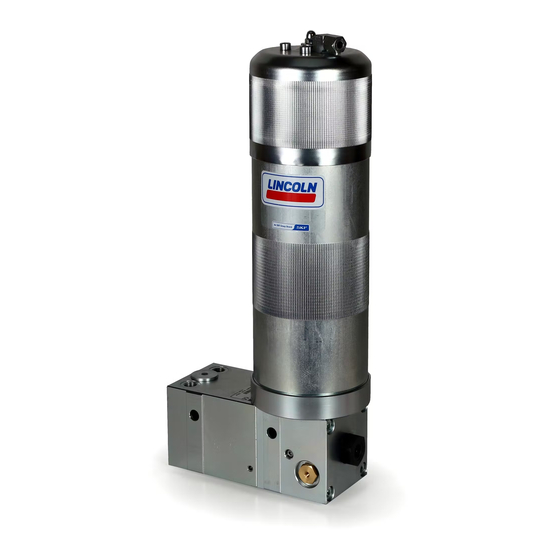
Hydraulically driven lubrication pump
Hide thumbs
Also See for Lincoln HTL 201:
- Assembly instructions manual (52 pages) ,
- Assembly instructions manual (58 pages)

Related Manuals for SKF Lincoln HTL 201


Summary of Contents for SKF Lincoln HTL 201
- Page 1 Installation instructions Hydraulically driven lubrication pump following machinery directive HTL 201 2006/42/EC 951-171-025-EN 2018/08/03 Version 02...
-
Page 2: Ec Declaration Of Incorporation
EC Declaration of incorporation EC declaration of incorporation following machinery directive 2006/42/EC, Annex II Part 1 B The manufacturer, SKF Lubrication Systems Germany GmbH, Walldorf Facilities, Heinrich-Hertz-Str. 2-8, DE - 69190 Walldorf, hereby declares that the partly completed machinery Designation:... -
Page 3: Legal Disclosure
© Copyright SKF. product All rights reserved. ○ intent or negligence Berlin Facilities Motzener Straße 35/37 ○ Use of non-original SKF spare parts. Warranty 12277 Berlin The instructions do not contain any informa- Liability for loss or damage resulting from Germany tion on the warranty. -
Page 4: Table Of Contents
Table of contents Table of contents EC declaration of incorporation ..............2 Legal disclosure ...................3 Explanation of symbols, signs and abbreviations ........7 Safety instructions .................9 Lubricants ................... 17 General safety instructions ..............9 General information ................17 General behaviour when handling the product ........9 Selection of lubricants ................17 Intended use ..................10 Material compatibility ................17... - Page 5 Table of contents Installation .................. 30 Initial start-up ................43 General information ................30 Inspections prior to initial start-up .............43 6.1.1 Installation bores ..................31 Inspections during initial start-up ............43 Hydraulic lines ..................32 Operation ..................44 Supply lines ...................32 Adjusting the output volume ...............33 Cleaning ..................
- Page 6 Table of contents Shutdown and disposal ............... 51 13.1 Temporary shutdown ................51 13.2 Final shutdown and disassembly ............51 13.3 Disposal ....................51 Spare parts ................. 52 14.1 Pump HTL201 ..................52 14.2 Retrofit kits ....................52 14.3 Cartridges ....................53 14.4 Adapter kits ....................53 14.5 Pressure control valve ................54 14.6...
-
Page 7: Explanation Of Symbols, Signs And Abbreviations
Explanation of symbols, signs and abbreviations Explanation of symbols, signs and abbreviations The following abbreviations may be used within these instructions. Symbols within safety notes mark the kind and source of the hazard. General warning Dangerous electrical voltage Risk of falling Hot surfaces Unintentional intake Crushing hazard... - Page 8 Explanation of symbols, signs and abbreviations Abbreviations and conversion factors regarding °C degrees Celsius °F degrees Fahrenheit approx. approximately Kelvin Ounce i.e. that is Newton fl. oz. fluid ounce etc. et cetera hour inch poss. possibly second pounds per square inch if appl.
-
Page 9: Safety Instructions
1. Safety instructions 1. Safety instructions 1.2 General behaviour when handling the 1.1 General safety instructions ○ Safety-related protective and emergency product ○ The owner must ensure that safety infor- devices must not be removed, modified ○ The product may be used only in aware- or affected otherwise in their function mation has been read by any persons en- ness of the potential dangers, in proper... -
Page 10: Intended Use
1. Safety instructions 1.3 Intended use 1.4 Foreseeable misuse 1.5 Painting Supply of lubricants or chisel pastes within Any usage differing from the one stated in The pump is delivered in unpainted condi- a centralized lubrication system following these Instructions is strictly prohibited, par- tion and can be operated without painting. -
Page 11: Modifications Of The Product
1. Safety instructions 1.6 Modiications of the product 1.8 Inspections prior to delivery Reference on Pressure Equipment Directive 2014/68/EU Unauthorized conversions or modifica- The following inspections were carried out Because of its performance data the product tions may result in unforeseeable impacts prior to delivery: does not achieve the limit values defined in on safety. -
Page 12: Markings On The Product Htl201 With 1.5 L Steel Reservoir
Warning of hot surfaces Model: ________________________________ Wear appropriate eye protec- P. No. ________________________________ tion when filling the 1.5 l steel reservoir S. No. ________________________________ SKF Lubrication Systems Germany GmbH HTL201-XXXXX-X Model: XXX-XXXXX-X P. No.: XXXXXXXXXXXXXXXX S. No.: XXX bar / X XXX psi... -
Page 13: Persons Authorized To Operate The Pump
1. Safety instructions 1.15 Brieing of external technicians 1.12 Persons authorized to operate the 1.13 Operation pump The following must be observed during Prior to commencing the activities, external commissioning and operation. technicians must be informed by the opera- 1.12.1 Operator ○... -
Page 14: Transport, Installation, Maintenance, Malfunctions
1. Safety instructions ○ Ensure through suitable measures that ○ Undertake drilling at non-critical, non- 1.17 Transport, installation, maintenance, movable or detached parts are immobi- malfunctions, repair, shutdown, load bearing parts only. Use any available lized during the work and that no limbs disposal. -
Page 15: Initial Commissioning / Daily Start-Up
1. Safety instructions ○ Observe the specified tightening torques. 1.18 Initial commissioning / daily start-up 1.19 Cleaning When tightening, use a calibrated torque ○ Risk of fire and explosion when using Ensure that: wrench. ○ All safety devices are completely available inflammable cleaning agents. -
Page 16: General Residual Risks
1. Safety instructions 1.20 General residual risks Residual risk Possible in life cycle Remedy Keep unauthorized persons away. Personal injury/ material damage due A B C G H K No people may remain under suspended loads. to falling of raised parts Lift parts with adequate lifting devices. -
Page 17: Lubricants
2.3 Material compatibility 2.2 Selection of lubricants Lubricants are used specifically for certain SKF considers lubricants to be an element Lubricants must generally be compatible application purposes. In order to fulfil their of system design. A suitable lubricant is se-... -
Page 18: Ageing Of Lubricants
(e.g. "bleeding"). packaging, if any, have to be Please contact SKF. if you have further ques- observed. tions regarding lubricants. You may request an overview of the lubri- cants tested by SKF. -
Page 19: Overview, Functional Description
3. Overview, functional description 3. Overview, functional description Overview Fig. 1 1 Reservoir/cartridge The reservoir with a follower piston resting on the lubricant stores the lubricant. For types of reservoirs and cartridges see: Pages 27-29. 1.1 Reservoir venting device The reservoir vent (1.1) is positioned on the 1.5 l steel reservoir. - Page 20 3. Overview, functional description Overview Fig. 2 5 Vent screw Serves to vent the lubricant. To do so, after filling the reservoir the vent screw (5) must be loosened there leaks a small amount of lubri- cant. Then firmly tighten the vent screw again. 6 Filler fitting (for 1.5 l steel reservoir only) The filler fitting serves to fill the reservoir via a transfer pump.
- Page 21 3. Overview, functional description Overview Fig. 3 11 Pressure relief valve The pressure relief valve (11) protects the pump and the lubrication system components against too high pressure. There are available pumps with a 120 bar respectively 270 bar pressure control valve. 951-171-025 - 21 - Version 02...
-
Page 22: Technical Data
4. Technical data 4. Technical data 4.1 Mechanics Operating temperature range of the pump -25 °C to +75 °C The indicated operating temperature range of the pump presupposes the suitability of the lubricant used for the actually existing operating tem- perature. -
Page 23: Nominal Output Volumes
4. Technical data 4.2 Nominal output volumes Pump element C7 or K7 Nominal output per stroke 0.22 cm This information applies for greases of NLGI class 2 at 40 °C and 100 bar counterpressure and the hydraulic operating pressure indicated in the diagram. Out- put volumes can be increased or reduced by turning the throttle into the plus or minus direction. -
Page 24: Tightening Torques
4. Technical data Overview Fig. 4 4.3 Tightening torques Adhere to the stated tightening torques. Pos. Component Tightening torque Pump element with integrated check valve 25 Nm ± 2.0 Nm Emergency lubrication fitting 14 Nm ± 1.0 Nm Vent screw 3 Nm ±... -
Page 25: Delivery, Returns, And Storage
This particularly applies for parts made out of plastic and rubber (embrittlement) as well 5.3 Storage as for components primed with SKF products are subject to the following lubricant (ageing). storage conditions: ○ dry, dust- and vibration-free in closed premises ○... -
Page 26: Mechanical Connection
6. Installation 5.4 Mechanical connection Minimum assembly dimensions 1.5 l steel reservoir Fig. 5 5.4.1 Minimum assembly dimensions Ensure sufficient space for maintenance work or for a possible disassembly of the product by leaving a free space of at least 100 mm into each direction in addition to Minimum assembly the stated dimensions, see page 28. - Page 27 6. Installation Minimum assembly dimensions KF XF and ST FX reservoirs Fig. 6 Minimum assembly dimensions KF XF ST XF A* = * with extended piston rod 951-171-025 - 27 - Version 02...
- Page 28 6. Installation Minimum installation dimensions KF oil reservoir and 500 ml cartridge Fig. 7 Minimum assembly dimensions Cartridge 500 ml 951-171-025 - 28 - Version 02...
- Page 29 4. Technical data Minimum installation dimensions 380, 310 and 150 ml cartridges Fig. 8 Minimum assembly dimensions Cartridges 380 / 310 ml 150 ml 194 mm 48.5 mm 175 mm 185 mm 951-171-025 - 29 - Version 02...
-
Page 30: Installation
6. Installation 6. Installation 6.1 General information Only qualified technical personnel may in- stall, operate, maintain, and repair the prod- ucts described in these Instructions. During assembly and particularly during any drilling work always pay attention to the following: ○ Other units must not be damaged by the assembly. -
Page 31: Installation Bores
6. Installation 6.1.1 Installation bores Installation bores Fig. 9 The product is fastened on the 2 mount- ing bores (7). For correct installation the pump housing (2) has to be underlaid with a suitable distance piece (12) made of steel exceeding the diameter of the lubricant res- ervoir (1). -
Page 32: Hydraulic Lines
6. Installation 6.2 Hydraulic lines Connecting hydraulic lines Fig. 10 Use suitable hydraulic fittings and lines to connect the pump with the pressure con- nection P (8) and the return-line connection T (10) to the hydraulic circuit of the superior machine / the carrier system. -
Page 33: Adjusting The Output Volume
6. Installation 6.4 Adjusting the output volume Adjusting of the output volume Fig. 11 During pump operation the output volume must never be changed. The pump is factory-set to maximum output. • Switch off the hydraulic system of the su- perior machine or carrier system. -
Page 34: Filling With Lubricant
6. Installation 6.5 Filling with lubricant • Remove the tear-off lid (D) from the rod engages in the notch of the reservoir closure cap. grease cartridge and then screw the grease reservoir assy. to the HTL adapter. 6.5.1 Operation with lubricant cartridge •... -
Page 35: Operation With Bulk Grease Filling In The Press Reservoir
6. Installation 6.6 Operation with bulk grease illing in • Use the handle to slowly pull the drive Fill in lubricant Fig. 14 the press reservoir rod together with the follower piston backward to that extent that the groove in •... -
Page 36: Reservoir For Oil
6. Installation 6.7 Reservoir for oil Reservoir for oil assembled Fig. 15 • Before the initial equipment or replace- ment of a reservoir for oi (1) or with a press reservoir the cartridge housing must be provided with an adapter (1.2 to Item. -
Page 37: Initial Placement Of A Cartridge
6. Installation 6.8 Initial placement of a cartridge Initial placement of a cartridge Fig. 16 • Lightly grease the O-ring included in the adapter. • Cut off the tip of the threaded collar of a new cartridge. • Insert cartridge into bore by pushing it slightly and then hand-tighten it to the housing. -
Page 38: Replacing The Cartridge
6. Installation 6.9 Replacing the cartridge Change of cartridge, Fig. 17 • Switch off the carrier device. • Remove the old cartridge unscrewing it anticlockwise. • Cut off the tip of the threaded collar of a new cartridge. • Lightly press the follower piston until grease leaks from the cartridge. -
Page 39: Filling The 1.5 L Steel Reservoir With Lubricant
6. Installation 6.10 Filling the 1.5 l steel reservoir with Filling the 1.5 l steel reservoir with lubricant Fig. 18 lubricant • Place the transfer pump with a proper matching part onto the filler fitting (6). • Switch the transfer pump on and fill the reservoir until lubricant leaks from the bore (1.1) (maximum filling of reservoir). -
Page 40: Venting Of The Pump
6. Installation 6.11 Venting of the pump Venting of the pump Fig. 19 Vent the pump after each filling of the reser- voir. By doing so a possible functional failure of the pump due to air inclusions can be avoided. During the reservoir filling pro- cedure the vent screw must not be open. -
Page 41: Emergency Lubrication
6. Installation 6.12 Emergency lubrication Emergency lubrication via emergency lubrication fitting Fig. 20 • Place the transfer pump with a proper matching part onto the emergency lubri- cation fitting (4). • Switch the transfer pump on and carry out an emergency lubrication until the connected lubrication points are provided with a sufficient amount of lubricant. -
Page 42: Lubrication Line Connection
6. Installation 6.13 Lubrication line connection ○ The lubricant flow should not be impeded Observe the following installation instruc- CAUTION tions for safe and smooth operation. by the installation of sharp elbows, angle valves, gaskets protruding to the inside, ○ Use clean components and primed lubri- Risk of falling or cross-section changes (big to small). -
Page 43: Initial Start-Up
7. Initial start-up 7. Initial start-up In order to warrant safety and function, a person assigned by the operator must carry out the following inspections. Immediately eliminate detected deficiencies. Deficiencies may be remedied by an authorized and qualified specialist only. Start-up check list 7.1 Inspections prior to initial start-up Mechanical connections carried out correctly... -
Page 44: Operation
8. Operation 8. Operation SKF products operate automatically to the greatest possible extent. Basically, activities during standard opera- tion are limited to: ○ Filling with lubricant (see 6.5) ○ Venting after filling with lubricant (see 6.11) ○ Cleaning / replacing the oil strainer (see 10.1) -
Page 45: Cleaning
To do so, contact the SKF Customer Service. and rinse off with clear water. Thus the formation of lye stone is Make sure to keep the reser- avoided. -
Page 46: Maintenance
10. Maintenance Maintenance Regular and appropriate maintenance is a prerequisite to detect and clear faults in time. The specific timelines have to be determined, verified at regular intervals and adapted, if necessary, by the operator based on the operating conditions. If needed, copy the table for regular mainte- nance activities. -
Page 47: Clean Or Replace Oil Strainer
10. Maintenance 10.1 Clean or replace oil strainer Clean or replace oil strainer Fig. 21 The oil strainer must be cleaned or replaced every 1,000 operat- ing hours. • Switch off the hydraulic system of the superior machine • Remove fitting of hydraulic connection P •... -
Page 48: Troubleshooting
11. Faults Troubleshooting Fault table 2 Fault Possible cause Remedy ○ Hydraulic system of carrier device is switched off ○ Switch the hydraulic system on ○ Pressure in the hydraulic system is too low (< 80 bar) ○ Check the hydraulic system ○... -
Page 49: Repairs
12. Repairs Repairs 12.1 Replacing the pressure control valve Replace pressure control valve Fig. 22 WARNING To reach the pressure relief Risk of injury valve, depending on the side of Before carrying out any repair work, attachment of the pump, it may take at least the following safety be necessary to disassemble the measures:... -
Page 50: Replace The 1.5 L Steel Reservoir
13. Shutdown and disposal 12.2 Replace the 1.5 l steel reservoir Replace reservoir Fig. 23 Reservoir should be empty when replacing it. When removing the reservoir, the lubricant inside will leak. To replace the reservoir proceed as follows: • A strap wrench may be required to loosen the steel reservoirs. -
Page 51: Shutdown And Disposal
13. Shutdown and disposal Shutdown and disposal 13.1 Temporary shutdown 13.3 Disposal Temporarily shut the system down by: Countries within the European Union ○ switching off the superior machine. Parts made of plastic or metal Disposal should be avoided or minimized 13.2 Final shutdown and disassembly wherever possible. -
Page 52: Spare Parts
14. Spare parts Spare parts 14.1 Pump HTL201 Fig. 24 Designation Qty. Part number HTL201 with pump element C7 and 120 bar pressure control valve 642-41184-1 HTL201 with pump element K7 and 120 bar pressure control valve 642-41184-2 HTL201 with pump element K7 and 270 bar pressure control valve 642-41184-4 14.2 Retroit kits Fig. -
Page 53: Cartridges
14. Spare parts 14.3 Cartridges Fig. 26 Designation Qty. Part number Cartridge with chisel paste, 150 ml 642-37608-4 Cartridge with EP 2 grease, 150 ml 642-37609-3 Cartridge with chisel paste, 310 ml 642-37636-2 Cartridge with EP 2 grease, 310 ml 642-37609-4 Fig. -
Page 54: Pressure Control Valve
14. Spare parts 14.5 Pressure control valve Fig. 28 Designation Qty. Part number 270 bar pressure control valve 235-14343-2 120 bar pressure control valve 235-14343-5 14.6 Oil strainer Fig. 29 Designation Qty. Part number Oil strainer screw G x 17, 100 μm 447-72394-1 14.7 Closure screws Fig. -
Page 55: Filler Fitting For 1.5 L Steel Reservoir
14. Spare parts 14.8 Filler itting for 1.5 l steel reservoir Fig. 31 Designation Qty. Part number Filler fitting 1/8“ 251-14109-6 14.9 Emergency lubrication itting Fig. 32 Designation Qty. Part number Emergency lubrication fitting 251-14073-9 14.10 Flat packing for 1.5 l steel reservoir Fig. - Page 56 951-171-025 2018/05/03 Version 02 SKF Lubrication Systems Germany GmbH Walldorf Facilities Heinrich-Hertz-Str. 2-8 DE - 69190 Walldorf Phone: +49 (0) 6227 33-0 Fax: +49 (0) 6227 33-259 E-mail: Lubrication-germany@skf.com www.skf.com/lubrication...
Need help?
Do you have a question about the Lincoln HTL 201 and is the answer not in the manual?
Questions and answers