Sign In
Upload
Download
Table of Contents
Contents
Add to my manuals
Delete from my manuals
Share
URL of this page:
HTML Link:
Bookmark this page
Add
Manual will be automatically added to "My Manuals"
Print this page
×
Bookmark added
×
Added to my manuals
Manuals
Brands
SKF Manuals
Water Pump
SKF-MPB-PUMP-1/1
Original operating instructions
SKF –MPB–PUMP-1/1 Original Operating Instructions
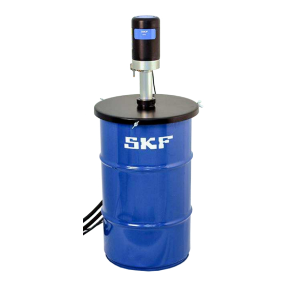
Pneumatic barrel pump
Hide thumbs
1
Table Of Contents
2
3
4
5
6
7
8
9
10
11
12
13
14
15
16
17
18
19
20
21
22
23
24
25
26
27
28
29
30
31
32
33
34
page
of
34
Go
/
34
Contents
Table of Contents
Troubleshooting
Bookmarks
Table of Contents
Table of Contents
Eu Declaration of Conformity
Eu Declaration of Conformity
Legal Disclosure
Explanation of Symbols, Signs and Abbreviations
Foreseeable Misuse
General Behaviour When Handling the Product
General Safety Instructions
Intended Use
Safety Instructions
Modifications to the Product
Notes Concerning the Type Identification Plate
Other Applicable Documents
Operation
Stopping the Pump in an Emergency
Transport, Installation, Maintenance, Malfunctions and Repairs
Persons Authorised to Operate the Device
Operator
Mechanical Specialist
Electrician
Providing Briefing for External Technicians
Provision of Personal Protective Equipment
Cleaning
Lubricants
Commissioning and Daily Start-Up
General Information
Lubricant Selection
Ageing of Lubricants
MPB Pump General Description
Material Compatibility
Commissioning
Main Components
Periodic Inspections
Troubleshooting
Malfunctions
Troubleshooting Table
Technical Information
Specifications Table
Pump Output Curve
MPB Pump Configurations
Designation and Order Codes
Shutdown, Decommissioning and Storage
Final Decommissioning
Storage
Spare Parts
Pneumatic Barrel Pump 1:20
Temporary Shutdown
MPB 1:20 Pump General Description
Commissioning
Main Components
Specifications Table
Technical Specifications of MPB 1:20
Output Curve of MPB 1:20
MPB 1:20 Pump, Configuration Options
Designation and Order Codes
Spare Parts MPB 1:20
Advertisement
Quick Links
1
Mechanical Specialist
2
Spare Parts
Download this manual
MPB
Pneumatic barrel pump
(Enslish translation of operating and maintenance instructions compliant with EU Directive
2006/42/EC)
Table of
Contents
Previous
Page
Next
Page
1
2
3
4
5
Advertisement
Table of Contents
Need help?
Do you have a question about the SKF–MPB–PUMP-1/1 and is the answer not in the manual?
Ask a question
Questions and answers
Related Manuals for SKF SKF–MPB–PUMP-1/1
Water Pump SKF SKF-MPB-PUMP-1/4 Original Operating Instructions
Pneumatic barrel pump (34 pages)
Water Pump SKF Spandau Pumpen PSR Series Assembly Manual And Corresponding Operating Manual
Centrifugal pump (32 pages)
Water Pump SKF SP/EY28 Assembly Instructions Manual
Hydraulic single-piston pump (38 pages)
Water Pump SKF Lincoln FlowMaster II 85878 User And Maintenance Instructions
B series (21 pages)
Water Pump SKF Lincoln J Series Installation Instructions Manual
2 1/2 in air motor chassis high pressure pump 50:1 (20 pages)
Water Pump SKF Linkoln Pile Driver III C Series User And Maintenance Instructions
(12 pages)
Water Pump SKF LINCOLN A Series User And Maintenance Instructions
Rotary driven electric pump (64 pages)
Water Pump SKF Lincoln 85552 Installation And Maintenance Manual
Flowmaster 24 v dc rotary driven electric pump (30 pages)
Water Pump SKF MityVac MV7201 User And Maintenance Instructions
Fluid evacuator plus (8 pages)
Water Pump SKF Multilube Operation And Service Manual
Central lubrication system pumping unit (32 pages)
Water Pump SKF KFG Assembly Instructions Manual
Piston pump aggregate for vehicle lubrication (108 pages)
Water Pump SKF M Series Assembly Instructions Manual
Gear, gerotor, vane, and multi-line pump units (28 pages)
Water Pump SKF Lincoln FlowMaster II User And Maintenance Instructions
Hydraulic pump (76 pages)
Water Pump SKF LINCOLN CLP Assembly Instructions Manual
Lubrication pump for progressive systems (52 pages)
Water Pump SKF MKU Series Manual
(102 pages)
Water Pump SKF LINCOLN P603M Assembly Instructions Manual
Lubrication pump for multi-line lubrication systems (84 pages)
This manual is also suitable for:
Skf–mpb–pump-1/4
Mpb series
Skf–mpb–pump-1 series
Skf–mpb–pump-1/8
Table of Contents
Save PDF
Print
Rename the bookmark
Delete bookmark?
Delete from my manuals?
Login
Sign In
OR
Sign in with Facebook
Sign in with Google
Upload manual
Upload from disk
Upload from URL


Need help?
Do you have a question about the SKF–MPB–PUMP-1/1 and is the answer not in the manual?
Questions and answers